T08099
TECHNICAL MANUAL BM 15
23
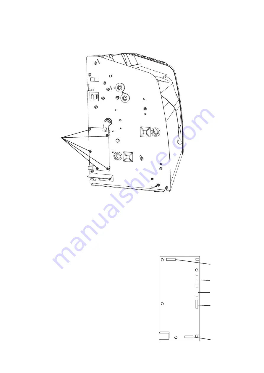
REP 2.13 PRINTED CIRCUIT BOARD
Removal
Remove the Rear Cover, according to REP 2.3.
Remove the Left Cover, according to REP 2.1.
Remove the screws [A].
Note the position of the
wires, see picture below, and disconnect the
connectors.
Remove the printed circuit board.
1.
2.
3.
4.
5.
Replacement
Reverse the removal procedure.
1.
[A]
P1
P7
P5
P4
P3
Summary of Contents for BM 15
Page 1: ...A BOOKLET MAKER BM 15 Operator Manual 11 October 2006 Part no 107 102306 Doc no T10162 ...
Page 2: ...B ...
Page 3: ...C ...
Page 4: ...D ...
Page 5: ...E ...
Page 6: ...F ...
Page 7: ...G H I ...
Page 8: ...H ...
Page 9: ...I J ...
Page 10: ...J ...
Page 11: ...BOOKLET MAKER BM 15 TECHNICAL MANUAL SERVICE MANUAL PARTS LIST 9 October 2006 ...
Page 12: ......
Page 20: ...TECHNICAL MANUAL BM 15 T08099 10 ...


