20 September 2006, Rev 0.01
3-54
SENSORS AND SWITCHES
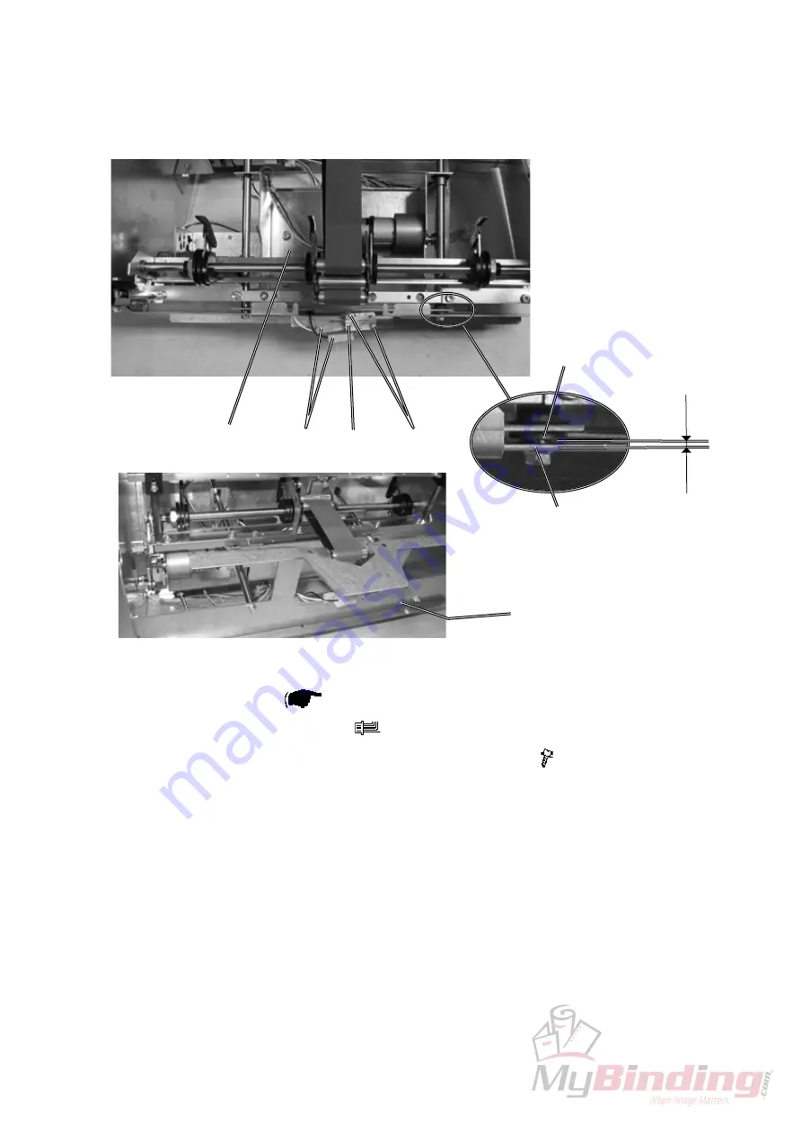
3.5.16 SW1 BACK JOGGER MOTOR (M11) HOME POS. SWITCH
Removal
1. Remove in-feed unit (
3.4.1 ).
2. Disconnect the connectors [A] (
x1 ).
3. Remove the screws [B] and remove the micro switch [C] ( x2 ).
Installation
1. Reverse the removal procedure
Adjustment
1. Loosing the rack by removing screw [D], which is holding the rack in place so
the jogger assembly [E] can be moved towards the switch.
2. Adjust the switch so it clicks when the distance [F], between bushing in the
jogger assembly [G] and the bracket [H], is 0,5 – 1 mm.
3. Put the rack back in place and mount the screw.
[B]
[C]
[D]
[H]
[G]
[F]
[E]
[A]


