Power and Control
Plockmatic PowerSquare™ 160 - Service Training Workbook
45
10.2
Control
The machine is organised around a CAN Bus. The Controller Area Network (CAN
bus) was originally developed by Robert Bosch in 1986 for automotive applications.
CAN is a robust bus standard designed to allow micro-controllers and devices to
communicate with each other in applications without a host computer or complex
dedicated wiring in between.
Each micro-controller on the CAN bus is called a ‘node’. In the PSQ160, each of the
control PCBs and the GUI have micro-controllers and are therefore nodes. Each
node has a unique number. See
and
The GUI provides overall control and user input. The other nodes control local
functions but are instructed from the GUI and sensor input:
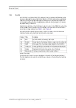
Table 1. Node list
If a fault occurs, an error code is displayed on the GUI, for example: E38.307.0.
The first digits are the node ID and tell the user where in the machine the fault has
occurred.
Node
Title
Function
05
GUI
Overall control, monitoring, user input
36
Rotator
Paper input to the bridge, rotation, edge or centre reference
32
Uplift
Lifts paper from the bridge infeed height to the PSQ160
38
Transport
Infeed, gathering and transport to the folder via the stapler
68
Stapler
Stapling/clinching and measuring book thickness
64
Bookmaker Folding, spine-forming, trimming and outfeed
Summary of Contents for Morgana PowerSquare 160
Page 72: ...Glossary of booklet making terms 68 Plockmatic PowerSquare 160 Service Training Workbook...
Page 73: ......
Page 74: ......
Page 75: ......

