Power and Control
46
Plockmatic PowerSquare™ 160 - Service Training Workbook
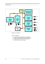
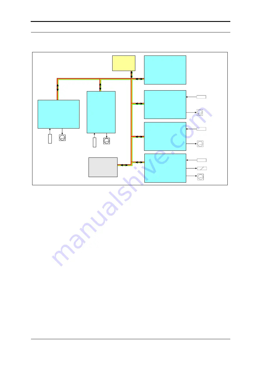
Figure 24. The CAN Bus
Refer to the following:
• 7.2.1 Bookmaker Module Electrical Layout Diagram
• 7.2.2 Staple - Clinch Module Electrical Layout Diagram
• 7.2.3 Transport Module Electrical Layout Diagram
• 7.2.5 Bridge Electrical Layout Diagram
Inverter
GUI
Rotate
900-308
PCB
M
Stepper
Motor
Sensors
CAN Bus
M
Stepper
Motors
Sensors
Uplift
900-310
PCB
Staple
900-308
PCB
Transport
900-303
PCB
Bookmaker
900-306
PCB
Power & Comms
Distribution
900-316 PCB
M
M
M
Stepper
Motors
Stepper
Motors
Stepper
Motors
Sensors
Sensors
Sensors
Solenoid
Node 32
Node 36
Node 05
Node 38
Node 68
Node 64
Summary of Contents for Morgana PowerSquare 160
Page 72: ...Glossary of booklet making terms 68 Plockmatic PowerSquare 160 Service Training Workbook...
Page 73: ......
Page 74: ......
Page 75: ......

