Power and Control
Plockmatic PowerSquare™ 160 - Service Training Workbook
51
10.4
DFA
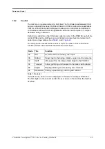
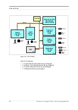
The 900-311 DFA input module PCB is the interface between the printer and the
finisher.
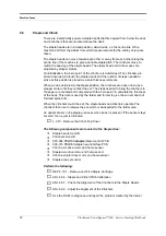
The following input and output signals are provided:
Status ouput signals from the PSQ160
Control input signals from the printer
LEDs are
RED
. LEDS 1, 2 & 3 must be
ON to let the PSQ160 run online.
LEDs are
GREEN
.
LED1
ST0
S0
LED off = Offline
LED9
CMD0
C0
Sheet exit
LED2
ST1
S1
LED off = Fault
LED10
CMD1
C1
End of set
LED3
ST2
S2
LED off = Full
LED11
CMD2
C2
Cycle up
LED4
ST3
S3
Pulse = sheet
delivered
LED12
CMD3
C3
End of job
LED5
ST4
S4
Pulse = set
delivered
LED13
CMD4
C4
LED6
ST5
S5
LED14
CMD5
C5
LED7
ST6
S6
LED15
CMD6
C6
LED8
ST7
S7
LED16
CMD7
C7
Cycle up - C2
Sheet exit - C0
End of set - C1
End of job - C3
Printer
Sheet delivered - S3
PSQ160
Set delivered - S4
Full - S2
Offline - S4
Fault - S1
Summary of Contents for Morgana PowerSquare 160
Page 72: ...Glossary of booklet making terms 68 Plockmatic PowerSquare 160 Service Training Workbook...
Page 73: ......
Page 74: ......
Page 75: ......


