background image


              Parameter 
 
Specification 

Current range 

(A) 

Suited main 

motor power 

(KW) 

Remark 

Description 

MAM880

20


8

20 

4

10 


Fan  has  three 
levels  of  current, 
such as 0.2-2.5A, 
1-5A  and  4-10A, 
determined 
according 

to 

fan’s current 

MAM880

40


16

40 

8

20 


MAM880

100


30

100 

15

50 


MAM880

200


80

200 

40

100 


MAM880

400


160

400 

80

200 


MAM880

600/5


100

600 

50

300 


4

Installation


1、 Installation of transducer  

The  transducer  shall  be installed  at  place  where  motor’s  line current  (rated current)  can  be measured, 

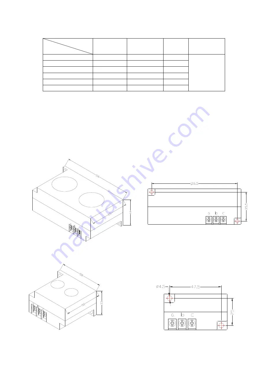
thus  controller  can  be  set  according  to  instructions  on  motor’s  name  plate,  the  detailed  dimensions  as 

followed:   


Figure 4.1.1. Structural dimensions of CT1 (ф36 through hole)            Figure 4.1.2. Install dimensions of CT1


A

B

B

A

Summary of Contents for MAM-880

Page 1: ...hen Plot electronic Co Ltd Address Sixth floor twenty fifth building TIAN JIAN industrial estate SHANG BAO road FU TIAN district SHEN ZHEN Telephone 0755 83172098 83172068 Postal code 518034 Fax 0755...

Page 2: ...lly before switch up Earthing terminal of this body part shall be earthed correctly the third type of earthing to increase product s capacity of resisting signal noise Motor s rated current current fo...

Page 3: ...matic control 17 3 Local manual control 17 4 Remote Manual Control 17 5 Network control 17 6 Temperature control of fan 18 7 Failure shutdown and emergency shutdown 18 6 Early warning and prompts 18 1...

Page 4: ...d by pressing this button when data are modified Menu is moved upwards when menu is selected Move down button Descending button Data at current position is descended by pressing this button when data...

Page 5: ...to move the black cursor to RUN PARAMETER press enter button to pop up submenu WELCOME USING SCREW COMPRESSOR AIR T 20 AIR P 0 60MPA NORMAL STOP C001 REMOTE RUN PARA USER PARA FACTORY PARA CALBR PARA...

Page 6: ...rimary menu press the move button to move the black slider to the USER PARA menu press the shift button to switch to the following menu Move the cursor to the P T SET menu then press enter button to s...

Page 7: ...P Control the stopping of the fan TIME SET HOST START 0008S When using the controller to protect the motor it is required that the time set here will not meet the impulse starting current of the motor...

Page 8: ...ration SEQ LOAD MPa The main air compressor searches for one device in the interlocking network for loading or starting when main air compressor s gas supply pressure is less than the value set here d...

Page 9: ...press set button switch to the factory parameters of the interface as follows Factory parameters run time phase sequence protection Frequency Selection and the time need check super password to chang...

Page 10: ...er frequency HIGH VOL V Controller detects the voltage higher than the set value the shutdown protection reported voltage is too high Set this value to 0000 the high voltage function is no function LO...

Page 11: ...A Displays the current controller sampling current values This value is the real value can not be set F A N A TARGET CUR 0000 Enter the current value the controller will detect user input value divide...

Page 12: ...cturers Password factory fixed ___________ Permissions Allows users to modify all the parameters the user password and the parameters of some manufacturers manufacturers selling password 6 Calibration...

Page 13: ...ors and operation time shown in following table table 2 1 1 when motor s working current is larger or equal to from 1 2 times and 3 0 times of set current Iactual Iset Time parameters 1 2 1 3 1 5 1 6...

Page 14: ...15 50 MAM880 200 80 200 40 100 MAM880 400 160 400 80 200 MAM880 600 5 100 600 50 300 4 Installation 1 Installation of transducer The transducer shall be installed at place where motor s line current...

Page 15: ...l dimensions of CT2 2 Controller Installation The controller is installed as plate Room should be left around controller for wiring The specific dimensions are as follows Figure 4 1 5 Controller struc...

Page 16: ...fan 15 terminals controls load valve 16 terminals controls angle shaped contactor 17 terminals controls star shaped contactor 18 terminals controls main contactor NOTE Eelectromagnetism coil shall be...

Page 17: ...ding until gas supply pressure is less than loading pressure If pressure is less than loading pressure the unloading button do not function Normal shutdown Press the button the load magnetic valve wil...

Page 18: ...filter Early warning for blockage of oil filter The controller can display the message on the text display to remind the operator that the air filter is blocked by checking the pressure difference swi...

Page 19: ...T 3 Non reversing Protection of Air Compressor When three phase supply phase sequence connected to the air compressor is not the same with that set for the controller the on site failure is displayed...

Page 20: ...power and contactors Overloaded Voltage too low tubes blocked Bearing Wear off or other mechanical failure or wrong set data etc Check the set data Voltage bearings tubes and other mechanical system...

Page 21: ...Temperature too high Bad vent condition Oil lacking etc Check the vent condition and lubricant amount etc Temperature Sensor Failure Cable off or PT1OO damaged Checking the wiring and PT100 Over Pres...

Page 22: ...Page 22 of 22 9 Electrical diagram 18 17 16 15 14 13 uc ua ub C1 RS 485 B A 1 FG 22 23 24 25 26 27 28 29 30 31 a CT2 21 20 19 2 3 4 5 6 7 8 9 10 b c A B C CT1 11 12...

Reviews: