background image

Zielpendel

13

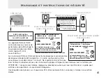
Das PLS5 Zielpendel kann für verschiedene zeitsparende Ausrichtungsaufgaben verwendet wer-
den. Für rechte Winkel: Für beständige Präzision bei der Herstellung oder Überprüfung eines
rechten Winkels verwenden Sie das PLS5 Zielpendel, um den Laserstrahl auf die Bodenfläche zu
übertragen. Zur Feststellung der Rechtwinkligkeit siehe Seite 8 dieser Bedienungsanleitung.
Installieren Sie den PLS5-Laser zur Feststellung der Rechtwinkligkeit immer auf dem Bodenstativ.
Das Zielpendel wurde so entwickelt, dass die Strahlen am besten in dieser Höhe zu sehen sind.

Zur Übertragung von Vertikallinien:
Zur schnellen und präzisen Übertragung von Vertikalmarkierungen
auf eine Wand:

1

. Stellen Sie die Vorderseite des PLS5-Lasers so gegen die Wand,

dass der Vorwärtsstrahl 1 auf der zu übertragenden Markierung ist.
(Wenn sich die Markierung auf dem Boden befindet, stellen Sie den
Abwärtsstrahl 2 auf die Markierung.)

2

. Platzieren Sie das Ziel so, dass seine Rückseite flach an der Wand

an der gewünschten Höhe anliegt, und verschieben Sie das Ziel, bis
der Aufwärtsstrahl 3 auf dem plastiküberzogenen Ziel zentriert ist.

3

. Markieren Sie das obere oder untere Ende der Zielpfeilstifte.

ZIELPENDEL

ABB. 13

Summary of Contents for PLS5

Page 1: ...OPERATING MANUAL PACIFIC LASER SYSTEMS The Professional Standard NEW PLS5 ...

Page 2: ...nt information Thousands of our customers will attest to the savings of time and money through the performance convenience and versatility of PLS laser tools You can be confident of prompt service to your laser should the need arise CONTENTS Introduction About The Company 1A 1B Maintenance Warranty Features Safety Labeling Instructions Beams Plumb 6 Level Square Check Calibration Magnetic Bracket ...

Page 3: ...tors for contractors PLS tools were developed out of necessity by professionals with over 50 years of experience in commercial and residential interior and exterior layout PLS founders were contractors first before becoming manufacturers of the finest point to point alignment tools in the world Point to point reference means you can plumb with a PLS5 or PLS3 literally from floor to ceiling or from...

Page 4: ...ork day can be spent on layout The PLS5 system gives square reference eas ily and quickly No more 3 4 5 The unique PLS cantilever design allows easy sight of the opposing reference points and is proven to be effective in installing curtain walls foundations columns skylights doors cabinetry and much more The portability and utility of PLS lasers make them attractive alignment tools when bubble via...

Page 5: ...cking and insurance costs Upon comple tion of the repair or replacement the unit will be returned to the customer freight prepaid The war ranty will not apply to this product if it has been misused abused or altered Without limiting the foregoing battery leakage dents or gouges to the plastic housing broken optic windows damage to the switch LED membrane are presumed to result from misuse or abuse...

Page 6: ...atures 3 BATTERY DOOR USE EITHER 3AA 1 5V ALKALINE OR NICAD BATTERIES INDICATOR LED ON GREEN TILT RED BATTERY LOW AMBER OPTIC WINDOWS 5 1 4 X 20 ACCESSORY MOUNT IN BASE OF EACH UNIT OPTIC WINDOWS 3 ON OFF ...

Page 7: ...SURE These labels are attached to every PLS laser These are not to be removed or defaced Safety Labeling Instructions WARNING LABEL ID CERTIFICATION LABEL GLOBALLY SOURCED FINAL ASSEMBLY IN U S A PATENT 6 938 360 1 800 601 4600 PLS 2550 KERNER BLVD SAN RAFAEL CA 94901 S N CLASS 2 LASER PRODUCT PLS3 COMPLIES WITH FDA STDS 21 CFR CHAP J 1040 10 11 EXCEPT FOR DEVIATION PURSUANT TO LASER NOTICE 60 OF ...

Page 8: ...eams of the PLS5 are 1 Forward Beam 2 Down Beam 3 Up Beam 4 Left Beam 5 Right Beam All PLS5 beams have the same brightness and are square to each other PLS3 The three beams of the PLS3 are 1 Forward Beam 2 Down Beam 3 Up Beam 2 3 3 2 ...

Page 9: ...loor track etc See Fig 2 Use the floor stand with your PLS5 or PLS3 to increase the sight angle of the 2 down beam The PLS3 and PLS5 can quickly survey existing conditions for plumb Use a tape and 3 up beam Position the laser near the structure Check any distance up or down the structure It is also possible to transpose marks from a roof or ceiling down to the floor Move the laser until the 3 up b...

Page 10: ...ripod or wall mount swivel and mark See Fig 5 When turning your PLS5 or PLS3 on a tripod be sure tripod head is perfectly level Error in marks can result with tripod out of level To survey existing conditions for level point in the direction to survey Using a tape or rod with a bench mark the variations in level or grade can be noted quickly at various distances See Fig 6 MARK FIG 4 FIG 5 MARK T A...

Page 11: ... line and center 1 forward beam on the center of the target Once centered move the pendulum target to square on 4 left beam or 5 right beam Make a mark on the floor or surface near the laser and the second mark at the desired distance from the laser See Fig 7 C L 8 FIG 7 MARK BEAM 1 BEAM 5 Square LAYOUT OR REFERENCE LINE C L MARK ...

Page 12: ...e 25 0 or more from a suitable wall or target See Fig 8 Point the 1 forward beam at the wall or target and carefully mark the center of elevation Swivel the PLS5 90 on its center until the 5 right beam is over the first mark Check to see if there is any difference in elevation from the center of 1 forward beam and the center of 5 right beam Repeat to check 4 beam At 50 0 the difference should not ...

Page 13: ...get 2 At 6 from the target mark the center of elevation of 1 forward beam on target 2 Swivel the laser on its cen ter and mark center of elevation at target 1 You now have two centers of elevation at each tar get Carefully measure the distance between centers of each set of marks If the distance is the same the laser is exactly level If there is a difference subtract one measurement from the other...

Page 14: ...t with the 2 down beam exactly centered on both axes over a cross mark See Fig 10 At the surface above mark both axes of 3 up beam Rotate the laser 180 and place the 2 down beam exactly centered on the same mark The 3 up beam should be exactly over the first mark If there is a difference between mark 1 and mark 2 the error of the plumb beam is one half that difference MARK DISTANCE FIG 10 ...

Page 15: ...cket a standard steel carpenter s framing square and one or more clamps and you have the ability to mount the laser in unlimited ways Clamp carpenter s square to concrete forms ladders wood studs etc Attach the PLS laser with magnetic mount as described above If you drill two small holes centered on the long section of the carpenter s square the square can be attached to unfinished drywall partiti...

Page 16: ...dulum target is designed so the beams are best seen at this height For transfer of vertical lines To transfer vertical marks quickly and accurately to a wall 1 Place the front of the PLS5 laser against the wall with the 1 forward beam on the mark to be transferred If the mark is on the floor place the 2 down beam over the mark 2 Place the target with its back flat against the wall at the desired h...

Page 17: ...cts The PLS5 partnered with our laser receiver gives the contractor the ability to accurately lay out a job site up to 250 feet even in the brightest outdoor conditions The PLS5 can also be used inside without the receiver for all point to point alignment tasks PLS5 System Interior Exterior System 14 C L FIG 7 MARK BEAM 1 BEAM 5 LAYOUT OR REFERENCE LINE C L MARK Beep Beep Beep Beep ...

Page 18: ...boards for concrete flatwork ELECTRICAL AND MECHANICAL CONSTRUCTION Rough in of conduit Rough in of waste and supply lines Rough in of natural gas supply lines FRAMING CONSTRUCTION Layout of control lines on concrete slabs decking and sub floors Alignment of exterior heavy gauge steel framing Layout alignment for commercial residential wood framing GLAZING CONSTRUCTION Layout install of curtain wa...

Page 19: ...us use 30 hrs continuous use Operating temp 0 F to 122 F 0 F to 122 F 18 C to 50 C 18 C to 50 C Storage temp 40 F to 158 F 40 F to 158 F 40 C to 70 C 40 C to 70 C Indicators Green light ON Green light ON Red light EXCEEDS Red light EXCEEDS TILT TILT Amber light BATTERY Amber light BATTERY LOW LOW Environmental Water resistant not Water resistant not submersible submersible Dimensions 2 X 4 X 4 3 4...

Page 20: ...PLS Lab Technicians PLS Pacific Laser Systems 2550 Kerner Blvd San Rafael CA 94901 www plslaser com 800 601 4500 ...

Page 21: ...MANUAL DE INSTRUCCIONES PACIFIC LASER SYSTEMS The Professional Standard NUEVO PLS5 ...

Page 22: ...ción Miles de nuestros clientes darán fe del ahorro de tiempo y dinero que se logra a través del rendimiento la conveniencia y la versatilidad de las herramientas láser PLS Además en el caso de que surja la necesidad puede confiar en un servicio inmediato para su láser CONTENIDO Introducción 1 Mantenimiento 2 Garantía 2 Características 3 Etiquetas de seguridad e instrucciones 4 Haces 5 Plomada 6 N...

Page 23: ...Una vez completada la reparación o el reemplazo la unidad será devuelta al cliente con flete previamente pagado La garantía no se aplicará si el pro ducto ha sido mal utilizado maltratado o alterado Además de lo anterior el derrame de la pila las abolladuras o gubias en la cubierta plástica la rotura de las ventanas ópticas el daño del inter ruptor o la membrana del indicador luminoso se considera...

Page 24: ... LA BATERÍA UTILICE 3 PILAS ALCALINAS AA DE 1 5 V O NICAD ILED INDICADOR ENCENDIDO VERDE INCLINACIÓN ROJO BATERÍA BAJA ÁMBAR VENTANAS ÓPTICAS 5 MONTAJE PARA ACCESORIOS DE 1 4 X 20 EN LA BASE DE CADA UNIDAD VENTANAS ÓPTICAS 3 ON OFF ...

Page 25: ...XPOSICIÓN PELIGROSA A LA RADICACIÓN Estas etiquetas están adheridas a todos los láseres PLS No deben retirarse ni dañarse Etiquetas de seguridad e instrucciones ETIQUETA DE ADVERTENCIA N º DE ETIQUETA DE CERTIFICACIÓNCERTIFICACIÓN P R E C A U C I Ó N RADIACIÓN LÁSER NO MIRE DIRECTAMENTE AL HAZ DE LUZ NI CON AYUDA DE INSTRUMENTOS ÓPTICOS POTENCIA MÁX DE EMISIÓN 1MW LONGITUD DE ONDA 635 670NM PRODUC...

Page 26: ...nce N º 2 Haz hacia abajo N º 3 Haz hacia arriba N º 4 Haz izquierdo N º 5 Haz derecho Todos los haces del PLS5 tienen el mismo brillo y están en escuadra entre sí PLS3Los tres haces del PLS3 son N º 1 Haz de avance N º 2 Haz hacia abajo N º 3 Haz hacia arriba 2 3 3 2 ...

Page 27: ...Consulte la Fig 2 Use la base del piso con el PLS5 o PLS3 para aumentar el ángulo de visualización del haz hacia abajo N º 2 El PLS3 y PLS5 pueden sondear rápidamente condiciones existentes para plomada Use una cinta y el haz hacia arriba N º 3 Coloque el láser cerca de la estructura Compruebe la distancia hacia arriba o hacia abajo de la estructura También es posible transponer marcas desde un te...

Page 28: ...ue Consulte la Fig 5 Cuando utilice el PLS5 o PLS3 sobre un trípode asegúrese de que la cabeza del trípode esté perfecta mente nivelada Un trípode mal nivelado puede producir errores en las marcas Para sondear condiciones existentes en relación con el nivel apunte en la dirección para sondear Use una cinta o varilla con un punto de referencia para anotar rápidamente las varia ciones en el nivel o ...

Page 29: ...l haz de avance N º central en el centro del objetivo Una vez centrado mueva el objetivo del péndulo en escuadra en el haz izquierdo N º 4 o el haz derecho N º 5 Haga una marca en el piso o la superficie cerca del láser y una segunda marca en la distancia deseada desde el láser Consulte la Fig 7 C L 8 FIG 7 MARCA HAZ N º 1 HAZ N º 5 Escuadra LÍNEA DE REPLANTEO O REFERENCIA C L MARCA ...

Page 30: ...able a 25 0 o más de distancia de una pared u objetivo adecuado Consulte la Fig 8 Coloque el haz de avance N º 1 en la pared u objetivo y marque detenidamente el centro de elevación Gire el PLS5 90 sobre su cen tro hasta que el haz derecho N º 5 esté sobre la primera marca Compruebe si hay alguna diferen cia en la elevación desde el centro del haz de avance N º 1 y el centro del haz derecho N º 5 ...

Page 31: ...l objetivo N º 2 Mueva el láser al objetivo N º 2 A 6 de distancia del objetivo marque el centro de elevación del haz de avance N º 1 en el objetivo N º 2 Gire el láser sobre su centro y marque el centro de elevación en el objetivo N º 1 Ahora tiene dos centros de elevación en cada objetivo Mida cuidadosamente la distancia entre los centros de cada conjunto de marcas Si la distancia es la misma el...

Page 32: ...s ejes sobre una marca de cruz Consulte la Fig 10 En la superficie arriba marque ambos ejes del haz hacia arriba N º 3 Gire el láser 180 y coloque el haz hacia abajo N º 2 exactamente en el centro en la misma marca El haz hacia arriba N º 3 debe estar exactamente sobre la primera marca Si hay una diferencia entre la marca N º 1 y la marca N º 2 el error del haz de plomada es responsable de mitad d...

Page 33: ...eto de péndulo está diseña do de modo que los haces se observen mejor a esta altura Para la transferencia de líneas verticales Para transferir marcas verticales de forma rápida y precisa a una pared 1 Coloque la parte frontal del láser PLS5 contra la pared con el haz de avance N º 1en la marca que desea transferir Si la marca está en el piso coloque el haz hacia abajo N º 2 sobre la marca 2 Coloqu...

Page 34: ...de modo que los haces se observen mejor a esta altura Para la transferencia de líneas verticales Para transferir marcas verticales de forma rápida y precisa a una pared 1 Coloque la parte frontal del láser PLS5 contra la pared con el haz de avance N º 1 en la marca que desea transferir Si la marca está en el piso coloque el haz hacia abajo N º 2 sobre la marca 2 Coloque el objetivo con su parte pl...

Page 35: ...iores y exteriores La fuerte luz solar ha limitado tradicionalmente el uso de láseres de haz visibles a proyectos en el interior El PLS5 junto con nuestro receptor láser ofrece al contratista la posibilidad de replantear con exactitud una obra de hasta más de 250 pies incluso en las condiciones exteriores con más luz El PLS5 también puede usarse en el interior sin el receptor para todas las tareas...

Page 36: ...mentos de hormigón CONSTRUCCIÓN ELÉCTRICA Y MECÁNICA Instalación de conductos Instalación de tuberías de desechos y suministros Instalación de tuberías de suministro de gas natural CONSTRUCCIÓN DE MARCOS Replanteo de líneas de control en hormigón cimientos plataformas y sobrepisos Alineación de marcos de acero de calibre pesado en exteriores Replanteo y alineación para marcos de madera comerciales...

Page 37: ...e de Ni Cad Tiempo de funcionamiento 30 horas de uso continuo 30 horas de uso continuo Temperatura de funcionamiento 0 F a 122 F 0 F a 122 F 18 C a 50 C 18 C a 50 C Temperatura de almacenamiento 40 F a 158 F 40 F a 158 F 40 C a 70 C 40 C a 70 C Indicadores Luz verde ENCENDIDO Luz verde ENCENDIDO Luz roja EXCEDE Luz roja EXCEDE INCLINACIÓN INCLINACIÓN Luz ámbar BATERÍA Luz ámbar BATERÍA BAJA BAJA A...

Page 38: ...Técnicos del laboratorio PLS PLS Pacific Laser Systems 2550 Kerner Blvd San Rafael CA 94901 www plslaser com o 800 601 4500 ...

Page 39: ...Manual de instrucciones PACIFIC LASER SYSTEMS The Professional Standard NUEVO PLS5 ...

Page 40: ... pro fesionales Miles de clientes pueden dar fe del ahorro de tiempo y dinero que se obtienen gracias al rendimiento la comodidad y la versatilidad de las herramientas láser de PLS Puede tener la confianza de que si fuera necesario obtendrá rápidamente asis tencia técnica sobre su equipo láser ÍNDICE Introducción 1 Mantenimiento 2 Garantía 2 Características 3 Etiquetado e instrucciones de segurida...

Page 41: ... vez completada la reparación o el reemplazo la unidad será devuelta al cliente con costes de envío previamente pagados La garantía no se aplicará al producto si ha sido utilizado indebidamente maltratado o alterado Además el derrame de la pila las mellas o abolladuras en la cubierta plástica la rotura de las ventanas ópticas los daños al interruptor o la membrana del indicador luminoso se consid ...

Page 42: ... USE 3 PILAS ALCALINAS AA DE 1 5 V O PILAS DE NÍQUEL CADMIO INDICADOR LED ENCENDIDO VERDE INCLINACIÓN ROJO BATERÍA BAJA ÁMBAR VENTANAS ÓPTICAS 5 SOPORTE ACCESORIO DE DE 1 4 X 20 EN LA BASE DE CADA UNIDAD ENCENDIDO APAGADO VENTANAS ÓPTICAS 3 ON OFF ...

Page 43: ... PUEDE SUPONER UNA EXPOSICIÓN PELIGROSA A LA RADIACIÓN Estas etiquetas se encuentran en todos los equipos láser PLS No se deben quitar ni desfigurar ETIQUETADO E INSTRUCCIONES DE SEGURIDAD ETIQUETA DE CERTIFICACIÓN CON NÚM DE ID REGISTRADO EN LA OFICINA DE PATENTES DE LOS EE UU P R E C A U C I Ó N RADIACIÓN LÁSER NO MIRE DIRECTAMENTE AL HAZ DE LUZ NI CON AYUDA DE INSTRUMENTOS ÓPTICOS POTENCIA MÁX ...

Page 44: ...cia abajo 3 haz hacia arriba 4 haz hacia la izquierda 5 haz hacia la derecha Todos los haces del equipo PLS5 presentan el mismo brillo y están dispuestos perpendicularmente entre sí PLS3 Los tres haces del equipo PLS3 son los siguientes 1 Haz hacia adelante 2 haz hacia abajo 3 haz hacia arriba 2 3 3 2 ...

Page 45: ... pie con el equipo PLS5 o PLS3 si desea aumentar el ángulo de visión del haz número 2 hacia abajo Los equipos PLS3 y PLS5 pueden evaluar rápidamente las condiciones existentes para la plomada Utilice una cinta y el haz número 3 hacia arriba Sitúe el láser junto a la estructura Compruebe las distancias hacia arriba y hacia abajo de la estructura También se puede realizar la transposición de marcas ...

Page 46: ...tar el ángulo de visión del haz número 2 hacia abajo Los equipos PLS3 y PLS5 pueden evaluar rápidamente las condiciones existentes para la plomada Utilice una cinta y el haz número 3 hacia arriba Sitúe el láser junto a la estructura Compruebe las distancias hacia arriba y hacia abajo de la estructura También se puede realizar la transposición de marcas desde un tejado o desde un techo hasta el sue...

Page 47: ...ntre el haz número 1 hacia delante en el centro del objetivo Una vez cen trado mueva el objetivo del péndulo hacia la escuadra en el haz número 4 hacia la izquierda o número 5 hacia la derecha Haga una marca en el suelo o en una superficie junto al láser y una segunda marca a la distancia deseada desde el láser Véase la figura 7 C L 8 FIG 7 HAZ 1 HAZ 5 ESCUADRA LÍNEA DE REFERENCIA O DISPOSICIÓN C ...

Page 48: ...jetivo ade cuado al efecto Véase la figura 8 Oriente el haz número 1 hacia delante en dirección de la pared o del objetivo y marque con cuidado el centro de elevación Haga girar el equipo PLS5 90 sobre su centro hasta que el haz número 5 hacia la derecha quede por encima de la primera marca Compruebe si hay diferencias en la elevación desde el centro del haz número 1 hacia delante y el del número ...

Page 49: ... objetivo 2 A unos 15 cm del objetivo marque el centro de elevación del haz número 1 hacia delante sobre el objetivo 2 Gire el equipo láser sobre su centro y marque el centro de elevación en el objetivo 1 Ahora tiene dos centros de elevación en cada objetivo Con cuidado mida la distancia entre los cen tros de cada conjunto de marcas Si la distancia es la misma significa que el láser está nivelado ...

Page 50: ...a abajo cen trado con exactitud en ambos ejes sobre una marca en forma de cruz Véase la figura 10 En la superficie de arri ba marque los dos ejes del haz número 3 hacia arriba Gire el láser 180 y coloque el haz número 2 hacia abajo centrado con exactitud en la misma marca El haz número 3 hacia arriba debe encontrarse exactamente sobre la primera marca Si existe alguna diferencia entre las marcas 1...

Page 51: ... el soporte magnético una escuadra de marco de acero estándar y una o más mordazas para poder colocar el láser en la posición deseada Puede fijar la escuadra en bloques de hormigón escaleras vigas de madera etc Acople el láser PLS con el soporte mag nético según lo descrito anteriormente Si taladra dos orificios pequeños centrados en la sección larga de la escuadra podrá acoplarla a divisiones de ...

Page 52: ...er un ángulo recto El objetivo del péndulo está diseñado de manera que los haces se vean mejor a esta altura Para la transferencia de líneas verticales Para transferir a una pared marcas verticales de un modo rápido y preciso 1 Sitúe la parte delantera del equipo láser PLS5 contra la pared con el haz número 1 hacia delante sobre la marca que se debe transferir Si la marca está en el suelo coloque ...

Page 53: ...junto con nuestro receptor láser brinda al contratista la posibilidad de diseñar con precisión un espacio de trabajo de más de 76 metros incluso en los días en que la luz del sol es más intensa El equipo PLS5 también se puede utilizar en interiores sin el receptor para todas las tareas de alineación punto a punto SISTEMA PLS5 INTERIOR EXTERIOR 14 C L FIG 7 MARCA HAZ 1 HAZ 5 LÍNEA DE REFERENCIA O D...

Page 54: ...ón CONSTRUCCIÓN MECÁNICA Y ELÉCTRICA Canalizaciones para conductos Canalizaciones para tubos de desagüe y suministro Canalizaciones para tubos de suministro de gas natural CONSTRUCCIÓN DE ESTRUCTURAS Disposición de líneas de control en placas de hormigón plataformas y subsuelos Alineación de estructuras exteriores de tubo de acero pesado Disposición y alineación para marcos de madera en aplicacion...

Page 55: ...bles de níquel cadmio Tiempo de funcionamiento 30 horas de uso continuo 30 horas de uso continuo Temp de funcionamiento De 0 F a 122 F De 0 F a 122 F de 18 C a 50 C de 18 C a 50 C Temp de almacenamiento De 40 F a 158 F De 40 F a 158 F De 40 C a 70 C De 40 C a 70 C Indicadores Luz verde Encendido Luz verde Encendido Luz roja EXCESO INCLINACIÓN Luz roja EXCESO INCLINACIÓN Luz ámbar BATERÍA Luz ámbar...

Page 56: ...Técnicos del laboratorio PLS PLSoPacific Laser Systems 2550 Kerner Blvd San Rafael CA 94901 EE UU www plslaser com o 800 601 4500 ...

Page 57: ...Manuale d uso PACIFIC LASER SYSTEMS The Professional Standard NUOVO PLS5 ...

Page 58: ...igliaia di clienti possono confermare il risparmio di tempo e denaro ottenuto grazie alle prestazioni alla convenienza e alla ver satilità degli strumenti laser PLS Potrete contare su un servizio rapido nel caso fosse necessario INDICE Introduzione 1 Manutenzione 2 Garanzia 2 Caratteristiche 3 Etichette di sicurezza e istruzioni 4 Fasci 5 Filo a piombo 6 Livellamento 7 Squadro 8 Controllo calibrat...

Page 59: ...e assicurazione Al termine della riparazione o sostituzione l unità verrà inviata al cliente con trasporto prepagato La garanzia non si applica ai prodotti usati in modo improprio danneggiati o modificati Senza limitazioni a quanto detto sopra le batterie scariche le ammaccature o intacca ture del contenitore in plastica la rottura delle finestre ottiche i danni alla membrana interruttore led sono...

Page 60: ...IA USARE TRE BATTERIE AA DA 1 5 V O AL NICAD INDICATORE A LED ACCESO VERDE INCLINAZIONE ROSSO BATTERIA SCARICA AMBRA FINESTRE OTTICHE 5 SUPPORTO ACCESSORI 1 4 X 20 ALLA BASE DI TUTTE LE UNITÀ ACCENSIONE SPEG NIMENTO FINESTRE OTTICHE 3 ON OFF ...

Page 61: ... etichette sono affisse su tutti i laser PLS Non devono essere rimosse o rese illeggibili Etichette di sicurezza e istruzioni UFFICIO BREVETTI REGISTRATI USA ETICHETTA DI CERTIFICAZIONE DI RICONOSCIMENTO A T T E N Z I O N E RADIAZIONE LASER NON GUARDARE DIRETTAMENTE IL RAGGIO NÉ GUARDARE DIRETTAMENTE CON STRUMENTI OTTICI POTENZA MAX USCITA 1MW LUNGHEZZA D ONDA 635 670NM PRODOTTO LASER CLASSE II GL...

Page 62: ...2 Raggio in basso n 3 Raggio in alto n 4 Raggio a sinistra n 5 Raggio a destra Tutti i raggi del PLS5 presentano la stessa inten sità luminosa e sono reciprocamente in squadro PLS3 I tre raggi del PLS3 sono n 1 Raggio in avanti n 2 Raggio in basso n 3 Raggio in alto 2 3 3 2 ...

Page 63: ...are il sup porto a pavimento con il PLS5 o PLS3 per aumentare l angolo di visuale del raggio n 2 Il PLS3 e PLS5 sono in grado di recuperare rapidamente le condizioni di filo a piombo esistenti Usare un nastro e il raggio n 3 verso l alto Posizionare il laser vicino alla struttura Controllare le distanze in alto e in basso alla struttura È anche possibile riportare le marcature da un tetto o un sof...

Page 64: ...tare e marcare Vedere la figura 5 Quando si ruota il PLS5 o PLS3 su un treppiede assicurarsi che la testina del supporto sia perfettamente livellata Eventuali errori nella marcatura comportano l er rato allineamento del treppiede Per recuperare le condizioni di livello esistenti puntare nella direzione per recuperare Usando un nastro o una barra con un riferimento è possibile annotare rapidamente ...

Page 65: ...il raggio n 1 sul cen tro del traguardo Una volta centrato spostare il traguardo sospeso per eseguire lo squadro con il raggio n 4 o n 5 Contrassegnare il pavimento o la superficie vicino al laser e un secondo con trassegno alla distanza desiderata dal laser Vedere la figura 7 C L 8 FIG 7 RAGGIO N 1 RAGGIO N 5 Squadro SCHEMA DELLA LINEA DI RIFERIMENTO C L CONTRASSEGNO CONTRASSEGNO ...

Page 66: ...ficie stabile 25 0 o più da una parete adatta o da un traguardo Vedere la fig 8 Puntare il raggio n 1 sulla parete o sul traguardo e contrassegnare con cura il centro dell ele vazione Ruotare di 90 il PLS5 sul proprio asse fino a che il raggio n 5 si porta sul primo con trassegno Controllare se esiste differenza nell elevazione tra il centro del raggio n 1 e il centro del raggio n 5 Ripetere il co...

Page 67: ... Spostare il laser sul traguardo n 2 A 15 cm 6 dal traguardo contrassegnare il centro di elevazione del raggio n 1 sul traguardo n 2 Ruotare il laser sul proprio asse e contrassegnare il centro di elevazione sul traguardo n 1 A questo punto si hanno due centri di elevazione per ogni traguardo Misurare accuratamente la distanza tra i punti di ciascuna coppia di marcature Se la distanza risulta la s...

Page 68: ... esattamente centrato su entrambi gli assi su una croce Vedere la figura 10 Sulla superficie sovrastante contrassegnare entrambi gli assi del raggio n 3 Ruotare il laser di 180 e posizionare il raggio n 2 esattamente centrato sullo stesso contrasseg no Il raggio n 3 dovrà essere esattamente sovrapposto al primo contrassegno Se si riscontra una differenza tra il contrassegno n 1 e n 2 l errore sul ...

Page 69: ...laser unitamente al supporto magnetico agli squadri standard e a uno o più morsetti si ha la possibilità di montare il laser in un numero illimitato di configu razioni Bloccare uno squadro alle forme in cemento alle scale travi in legno ecc Fissare il laser PLS con il supporto magnetico come descritto sopra Se si preparano due piccoli fori centrati sulla sezione lunga dello squadro questo può esse...

Page 70: ...n modo tale che la visibilità dei raggi sia ottimale a tale altezza Per riportare le linee verticali Per riportare i contrassegni rapidamente e con precisione su una parete 1 Posizionare la parte anteriore del laser PLS5 contro la parete con il raggio n 1 sul contrassegno da riportare Se il contrassegno è sul pavimento posizionare il raggio n 2 sul contrassegno 2 Posizionare il traguardo con la pa...

Page 71: ...n il ricevitore laser offre la capacità di tracciare con precisione un cantiere fino a 76 m 250 piedi anche in condizioni di massima illuminazione esterna Il PLS5 può essere usato anche all interno senza ricevitore per tutti i compiti di allinea mento Sistema PLS5 per interni e per esterni 14 C L FIG 7 CONTRASSEGNO RAGGIO N 1 RAGGIO N 5 SCHEMA DELLA LINEA DI RIFERIMENTO C L CONTRASSEGNO Beep Beep ...

Page 72: ...LETTRICHE E MECCANICHE Tracciamento dei condotti Tracciamento delle linee di alimentazione e scarico Tracciamento delle linee di alimentazione del gas naturale COSTRUZIONI SU TELAIO Tracciamento delle linee di controllo su pavimentazione in calcestruzzo rivestimenti e sotto pavimenti Allineamento di strutture in acciaio pesante esterne Tracciamento e allineamento per strutture in legno commerciali...

Page 73: ...zionamento 30 ore di uso continuo 30 ore di uso continuo Temperatura di esercizio da 0 F a 122 F da 0 F a 122 F da 18 C a 50 C da 18 C a 50 C Temperatura di conservazione da 40 F a 158 F da 40 F a 158 F da 40 C a 70 C da 40 C a 70 C Indicatori Luce verde ON ACCESO Luce verde ON ACCESO Luce rossa INCLINAZIONE ECCESSIVA Luce rossa INCLINAZIONE ECCESSIVA Luce color ambra BATTERIA SCARICA Luce color a...

Page 74: ...PLS Lab Technicians PLS Pacific Laser Systems 2550 Kerner Blvd San Rafael CA 94901 www plslaser com o 800 601 4500 numero verde USA ...

Page 75: ...Bedienungsanleitung PACIFIC LASER SYSTEMS The Professional Standard NEUES MODELL PLS5 ...

Page 76: ...en bereitzustellen Tausende unserer zufriedenen Kunden können bestätigen dass sie dank der Leistung Zweckmäßigkeit und Vielseitigkeit der PLS Laserwerkzeuge viel Zeit und Geld sparen Sie können sich darauf verlassen dass Sie im Bedarfsfall umgehend Kundendienst für Ihren Laser erhalten INHALT Einleitung 1 Wartung 2 Garantie 2 Produktmerkmale 3 Sicherheitskennzeichnung und hinweise 4 Laserstrahlen ...

Page 77: ...ird das System mit vorausbezahlter Fracht an den Kunden zurück geschickt Die Garantie gilt nicht wenn dieses Produkt einer falschen Verwendung Missbrauch oder Modifikation unterzogen wurde Ohne Einschränkung des Vorstehenden wird angenommen dass Batterielecks Beulen oder Furchen im Kunststoffgehäuse zerbrochene Optikfenster und Beschädigung der Schalter LED Membran das Ergebnis falscher Verwendung...

Page 78: ...KUNG VERWENDEN SIE ENTWEDER 3 AA 1 5 VOLT ALKALI ODER NI CAD BATTERIEN ANZEIGE LED EIN GRÜN NEIGUNG ROT BATTERIELADUNG SCHWACH GELB OPTISCHE FENSTER 5 1 4 X 20 ZUBEHÖRHALTERUNG IM UNTERTEIL JEDES GERÄTS EIN AUS OPTISCHE FENSTER 3 ON OFF ...

Page 79: ...ER STRAHLENEXPOSITION FÜHREN Diese Etiketten sind an jedem PLS Laser angebracht Sie dürfen nicht entfernt oder unkenntlich gemacht werden Sicherheitskennzeichen und hinweiSE WARNETIKETT ID NUMMER ZULASSUNGSETIKETT V O R S I C H T LASERSTRAHLUNG STARREN SIE NICHT IN DEN STRAHL UND SEHEN SIE IHN NICHT DIREKT MIT OPTISCHEN INSTRUMENTEN AN MAXIMALER STROMAUSSTOß 1MW WELLENLÄNGE 635 670NM LASERPRODUKT ...

Page 80: ...d 1 Vorwärtsstrahl 2 Abwärtsstrahl 3 Aufwärtsstrahl 4 Linker Strahl 5 Rechter Strahl Alle PLS5 Strahlen haben die gleiche Helligkeit und sind rechtwinklig zueinander PLS3 Die drei Laserstrahlen des PLS3 Lasers sind 1 Vorwärtsstrahl 2 Abwärtsstrahl 3 Aufwärtsstrahl 2 3 3 2 ...

Page 81: ...aser um den Sichtwinkel des Abwärtsstrahls 2 zu vergrößern Mit dem PLS3 und PLS5 Modell können Sie schnell bestehende Bedingungen auf Lothaltigkeit über prüfen Verwenden Sie ein Bandmaß und den Aufwärtsstrahl 3 Positionieren Sie den Laser in der Nähe der Struktur Prüfen Sie beliebige Abstände strukturaufwärts oder abwärts Es ist auch möglich Markierungen von einem Dach oder einer Decke auf den Bod...

Page 82: ...ss der Stativkopf völlig waagerecht ist Wenn das Stativ nicht waagerecht ist können sich Fehler in den Markierungen ergeben Um die Waagrechtigkeit bestehender Bedingungen zu überprüfen richten Sie den Strahl in die Vermessungsrichtung Mit einem Bandmaß oder einem Stab mit Höhenmarkierungen können Abweichungen in der Waagerechten oder Höhe schnell in ver schiedenen Entfernungen erfasst werden siehe...

Page 83: ...d center 1 forward beam on the center of the target Once centered move the pendulum target to square on 4 left beam or 5 right beam Make a mark on the floor or surface near the laser and the second mark at the desired distance from the laser See Fig 7 C L 8 ABB 7 STRAHL 1 STRAHL 5 Rechtwinkeligkeit REFERENZLINIE C L MARKIERUNG MARKIERUNG ...

Page 84: ... von einer geeigneten Wand oder einem geeigneten Ziel siehe Abb 8 Richten Sie den Vorwärtsstrahl 1 auf die Wand oder das Ziel und markieren Sie den Mittelpunkt der Höhe sorgfältig Drehen Sie den PLS5 Laser um 90 um seinen Mittelpunkt bis der rechte Strahl 5 über der ersten Markierung steht Überprüfen Sie ob eine Differenz in der Höhe vom Mittelpunkt des Vorwärtsstrahls 1 und dem Mittelpunkt des re...

Page 85: ...r Entfernung von ca 15cm vom Ziel den Höhenmittelpunkt des Vorwärtsstrahls 1 auf dem Ziel 2 Drehen Sie den Laser um seinen Mittelpunkt und markieren Sie den Höhenmittelpunkt auf Ziel 1 Jetzt haben Sie zwei Höhenmittelpunkte an jedem Ziel Messen Sie den Abstand zwischen den Mittelpunkten jeder Markierungsgruppe genau Wenn der Abstand gleich ist ist der Laser genau waagerecht Wenn sich eine Differen...

Page 86: ...r Kreuzmarkierung genau zentriert ist siehe Abb 10 Markieren Sie an der Oberfläche den Aufwärtstrahl 3 mit einer Kreuzmarkierung Drehen Sie den Laser um 180 und platzieren Sie den Abwärtsstrahl 2 so dass er genau auf der gleichen Markierung zentriert ist Der Aufwärtsstrahl 3 sollte genau über der ersten Markierung sein Wenn zwischen Markierung 1 und Markierung 2 eine Differenz besteht beträgt der ...

Page 87: ...s herkömmlichen Tischlerwinkels aus Stahl und einer oder mehrerer Klemmen können Sie den Laser auf unzählige Arten installieren Klemmen Sie den Zimmermannswinkel an Betonformteilen Leitern Holzpfosten etc an Installieren Sie den PLS Laser wie oben beschrieben mit der magnetischen Halterung Wenn Sie zwei kleine Löcher in der Mitte des langen Teils des Zimmermannswinkels bohren kann der Winkel mit S...

Page 88: ... so entwickelt dass die Strahlen am besten in dieser Höhe zu sehen sind Zur Übertragung von Vertikallinien Zur schnellen und präzisen Übertragung von Vertikalmarkierungen auf eine Wand 1 Stellen Sie die Vorderseite des PLS5 Lasers so gegen die Wand dass der Vorwärtsstrahl 1 auf der zu übertragenden Markierung ist Wenn sich die Markierung auf dem Boden befindet stellen Sie den Abwärtsstrahl 2 auf d...

Page 89: ...tbarem Strahl auf Projekte im Innenbereich beschränkt Der PLS5 Laser in Kombination mit unserem Laserempfänger ermöglicht dem Bauunternehmer das Layout einer Baustelle bis zu 60 70m selbst unter den hellsten Bedingungen im Freien PLS5 System für Innen Außenanwendungen 14 C L ABB 7 MARKIERUNG STRAHL 1 STRAHL 5 REFERENZLINIE C L MARKIERUNG Signalton Signalton Signalton Signalton ...

Page 90: ...noberbauarbeiten MECHANISCHE UND ELEKTROANLAGEN Einbau von Leitungsführungen Einbau von Entsorgungs und Versorgungsleitungen Einbau von Erdgasversorgungsleitungen RAHMENBAU Kontrolllinien auf Betonplatten Bodenbelägen und Unterböden Ausrichtung von schweren Stahlaußenrahmen Auslegung und Ausrichtung für Holzrahmen in Wohn und Gewerbegebäuden GLASBAU Ausrichtung und Installation von Fassadenprojekt...

Page 91: ...icad wiederaufladbar Nicad wiederaufladbar Betriebszeit 30 Stunden Dauerbetrieb 30 Stunden Dauerbetrieb Betriebstemperatur 18o C bis 50o C 18o C bis 50o C Lagertemperatur 40o C bis 70o C 40o C bis 70o C Anzeige Grüne Lampe EIN Grüne Lampe EIN Rote Lampe ÜBERSCHREITET Rote Lampe ÜBERSCHREITET NEIGUNG NEIGUNG Gelbe Lampe BATTERIE Gelbe Lampe BATTERIE SCHWACH SCHWACH Staub und Feuchteschutz Staub und...

Page 92: ...PLS Lab Technicians PLS Pacific Laser Systems 2550 Kerner Blvd San Rafael CA 94901 USA www plslaser com o Tel 1 800 601 4500 ...

Page 93: ...GUIDE D UTILISATION PACIFIC LASER SYSTEMS The Professional Standard NOUVEAU PLS5 ...

Page 94: ...gnement requise de façon efficace Des milliers de nos clients certifieront de l économie de temps et d argent réalisés grâce à la commoditéé polyvalence et performance des outils laser de PLS Et dans le cas où votre outil devrait être réparé vous pouvez être assuré d une attention immédiate et professionnelle CONTENU Introduction 1 Entretien 2 Garantie 2 Parties fonctionnelles 3 Marquage et Instru...

Page 95: ... sera renvoyé au client frais d envoi prépayés La garantie ne s appliquera pas à ce produit s il mon tre des signes de mauvaises ustilisations de chocs ou de bris Sans limitation à ce qui précède une fuite de pile des traces de coups ou de gouges sur le boîtier en matière plastique des fenêtres optiques brisées l en dommagement de la membrane d interrupteur de diode électroluninescente DEL seront ...

Page 96: ...TROIS 3 PILES AA NICKEL CADMIUM OU ALCALINES IVOYANT DEL EN MARCHE VERT INCLINÉ ROUGE PILES FAIBLES AMBRE OFTEN TRANSLATED AS ORANGE FENÊTRES OPTIQUES 5 ACCESSOIRE DE MONTAGE À FILETS DE 1 4 X 20 DANS LA BASE DE TOUTES LES UNITÉS FENÊTRES OPTIQUES 3 ON OFF ...

Page 97: ... entraîner une exposition à un rayonnement dangereux Ces étiquettes sont placées sur chaque laser PLS Elles ne doivent être ni enlevées ni laissées en condition illisible Marquage et instructions de sécurité ÉTIQUETTE D AVERTISSEMENT ÉTIQUETTE DE CERTIFICATION DU NUMÉRO D IDENTIFICATION GLOBALLY SOURCED FINAL ASSEMBLY IN U S A PATENT 6 938 360 1 800 601 4600 PLS 2550 KERNER BLVD SAN RAFAEL CA 9490...

Page 98: ...vers le bas n 3 faisceau vers le haut n 4 faisceau gauche n 5 faisceau droit Tous les faisceaux du PLS5 ont la même intensité et sont à angle droit l un par rapport à l autre PLS3 Les trois faisceaux du PLS3 sont nN 1 faisceau avant n 2 faisceau vers le bas n 3 faisceau vers le haut 2 3 3 2 ...

Page 99: ...Voir la figure 2 Pour accroître l angle de vue du faisceau n 2 vers le bas utilisez le socle de votre PLS5 ou PLS3 Les appareils PLS3 et PLS5 peuvent rapidement matérialiser les conditions d aplomb Utilisez un ruban à mesurer et le faisceau n 3 vers le haut Positionnez le laser près de la structure Contrôlez l une ou l autre des distances vers le haut ou vers le bas Il est également possible de tr...

Page 100: ...z Voir la figure 5 Lorsque vous faites pivoter votre PLS5 ou PLS3 sur un trépied assurez vous que la tête du trépied soit parfaitement au niveau Une erreur de marquage peut dépendre d un trépied n étant pas au niveau Pour vérifier les conditions actuelles de niveau pointez dans la direction à inspecter En utilisant un ruban à mesurer ou bâton de mesure d arpenteur les varia tions de niveau ou de p...

Page 101: ...t centrez le faisceau n 1 avant au centre de la cible Une fois centré déplacez la cible pendulaire à angle droit avec le faisceau n 4 ou n 5 gauche ou droit Faites une marque sur la surface du plancher près du laser et la seconde marque à la distance désirée du laser Voir la figure 7 C L 8 FIG 7 MARQUE FAISCEAU N 1 FAISCEAU N 5 Angle droit PLAN OU LIGNE DE RÉFÉRENCE C L MARQUE ...

Page 102: ...ne distance de 8 m ou plus d un mur ou cible adéquate Voir la fig ure 8 Pointez le faisceau n 1 avant sur le mur ou la cible et marquez soigneusement le point médi an de l élévation Faites pivoter le PLS5 de 90 autour de son centre jusqu à ce que le faisceau lumineux n 5 soit sur la première marque Vérifiez s il y a une différence d élévation quelconque entre le point médian du faisceau n 1 avant ...

Page 103: ...ible n 2 À 15 cm de la cible faites une marque au point médian de l élévation du faisceau n 1 avant sur la cible n 2 Faites pivoter le laser sur son centre et marquez le point médian de l éléva tion sur la cible n 1 Vous avez maintenant deux points de hauteur marqués sur chaque cible Mesurez avec soin la distance entre les deux marques de chaque cible Si la distance est la même c est que le laser ...

Page 104: ...nité exactement au centre des deux axes sur une marque en croix Voir la figure 10 Sur la surface mentionnée ci haut marquez les deux axes du faisceau n 3 vers le haut Faites pivoter le laser sur 180 et placez le faisceau n 2 du bas exacte ment au centre sur la même marque Le faisceau n 3 vers le haut devrait être exactement sur la première mar que S il y a une différence entre la marque n 1 et la ...

Page 105: ...standard de charpentier en acier et une ou plusieurs serres d attache et vous aurez la possibilité de monter le laser dans une infinité de positions Serrez l équerre de charpentier à des formes de coulage de béton échelles gou jons de bois etc Fixez le laser PLS avec le support magnétique comme décrit ci dessus Si vous percez deux petits trous centrés sur la section la plus longue de l équerre cel...

Page 106: ...tant La cible pendulaire est conçue de sorte que les faisceaux sont perçus plus facilement à cette hauteur Pour le transfert de lignes verticales Pour transférer des marques verticales sur un mur de façon rapide et précise 1 Placez le devant lu laser PLS5 contre le mur en dirigeant le faisceau n 1 avant sur la marque à transférer Si la marque est sur le plancher placez le faisceau n 2 du bas sur l...

Page 107: ...PLS5 utilisé conjointement avec notre récepteur laser procure aux sous traitants la possibilité de tracer un projet de façon précise jusqu à une distance dépassant 75 m même sous le soleil de midi Le PLS5 peut également être utilisé à l intérieur sans récepteur pour toutes les tâches d alignement point par point Système intérieur extérieur du PLS5 14 C L FIG 7 MARQUE FAISCEAU N 1 FAISCEAU N 5 PLAN...

Page 108: ...STRUCTION MÉCANIQUE ET ÉLECTRIQUE Cheminement brut de conduits Cheminement brut de circuits d alimentation et de décharge Cheminement brut de circuits de gaz naturel CONSTRUCTION DE CHARPENTE Disposition de lignes de contrôle sur dalles de béton patios et sous planchers Alignement de charpentes métalliques de fort calibre extérieures Disposition et alignement de charpentes de bois de constructions...

Page 109: ...geables Durée de fonctionnement de 30 heures en usage continu de 30 heures en usage continu Température d utilisation 18o C à 50o C 18o C à 50o C Température d entreposage 40o C à 70o C 40o C à 70o C Voyants Vert ON MARCHE Vert ON MARCHE Rouge EXCÈDE INCLINAISON Rouge EXCÈDE INCLINAISON Ambre PILES Ambre Ambre PILES Ambre Orange PILES FAIBLES Orange PILES FAIBLES Environnement À l épreuve des écla...

Page 110: ......

Page 111: ......

Page 112: ...Techniciens du labo PLS PLS Pacific Laser Systems 2550 Kerner Blvd San Rafael CA 94901 États Unis www plslaser com 800 601 4500 ...

Reviews: