background image

-1

0

Ω

Ω

EQP-102

AUTOMOTIVE MULTIMETER

USER MANUAL

Contents

Introduction

……………………………………………………………………….1

Safety

………………………………………………………………………………2

Getting Started

…………………………………………………………………6

Digital LCD Display………………………………………………………………7

Front Panel Description…………………………………………………………7

LCD Symbols……………………...…………………………………………………8

Push-button Functions

……………………………………………………9

Mo d e B u t t o n … … … … … … … … … … … … … … … … … … … … … … 9

Manual range & Stroke 4/2,Hz,%,ms,CYL Button………………………… 9

Data Hold /Backlight Button………………………………………………9

Relative Button………………………………………………………………11

Meter Functions

Voltage (V)……………………………………………………………………12

Resistance  (Ω)  ………………………………………………………………13 

Diode Check(

)……………………………………………………………14

Capacitance(CAP) …………………………………………………………15

Audible Continuity (

)……………………………………………………16

AC or DC Current (A) ………………………………………………………17

Temperature (

0

C /

0

F

) ………………………………………………………18

Frequency (Hz) ……………………………………………………………19

Dwell (

)…………………………………………………………………20

Duty Cycle (%)………………………………………………………………21

Ms – PULSE……………………….………………………………………22

RPM (

) ……………………………………………………………………24

IR Temperature Probe……………………………………………………….25

General Specifications

…………………………………………………………30

Electrical Specifications

…………………………………………………………31

Replacing the Battery…………………………………………………………34

Battery Installation…………………………………………………………35

Replacing the Fuses………………………………………………………………35

Trouble Shooting…………………………………………………………………36

Summary of Contents for EQP-102

Page 1: ...YL Button 9 Data Hold Backlight Button 9 Relative Button 11 Meter Functions Voltage V 12 Resistance Ω 13 Diode Check 14 Capacitance CAP 15 Audible Continuity 16 AC or DC Current A 17 Temperature 0 C 0 F 18 Frequency Hz 19 Dwell 20 Duty Cycle 21 Ms PULSE 22 RPM 24 IR Temperature Probe 25 General Specifications 30 Electrical Specifications 31 Replacing the Battery 34 Battery Installation 35 Replacin...

Page 2: ...to block the wheels on front wheel drive vehicles the parking brake does not hold the drive wheels Wear an eye shield when testing or repairing vehicles Exceeding the limits of this meter is dangerous This will expose you to serious or possibly fatal injury Carefully read and understand the cautions and the specification limits of this meter Voltage between any terminal and ground must not exceed ...

Page 3: ...0A terminals are protected by fuses To avoid possible injury or damage use only in circuits limited to 400mA or 20A for 30 seconds See also Fuse Replacement Safety Cont d IMPORTANT To maintain accuracy of the meter replace the discharged battery immediately when the battery symbol BAT appears on the meter display Avoid measuring error from outside interference Keep the meter away from spark plug o...

Page 4: ...5 6 Ω Ω Notes Getting Started his chapter will help you get started It describes the basic functions of the Meter ...

Page 5: ...4 Volts Terminal The Red test lead is used to measure Amps Volts Ohms TEMP Hz RPM Cap mS and Dwell The Black test lead is used in the Common COM terminal for all tests LCD DISPLAY SYMBOLS AND ANNUNCIATORS 8 8 8 8 LCD display reading Continuity BAT Low Battery Diode DATA HOLD Data Hold AUTO Auto Ranging AC Alternating Current or Voltage DC Direct Current or Voltage n nano 10 9 capacitance µ micro 1...

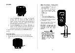
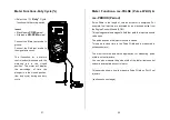
Page 6: ...he reading on the indicator The indication of HOLD will appear in the display 2 Press the DATA HOLD button again to return to normal operation Peak Hold The Peak Hold function captures the peak AC or DC voltage or current The meter can capture negative or positive peaks as fast as 1 millisecond in duration 1 Turn the function switch to the A or V position 2 Press and Hold the PEAK button until CAL...

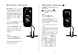
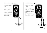
Page 7: ...utton to turn the backlighting ON 2 Press the BACKLIGHT button again to turn the backlighting OFF Meter Functions Voltage V Select the Volts V range with the rotary switch The meter will automatically select the best voltage V range Select DCV or ACV with the MODE button Insert Black lead in COM terminal Red lead in V Ω RPM terminal Touch the Black probe to ground or to the negative circuit Touch ...

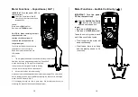
Page 8: ...ter Functions Diode Check IMPORTANT Turn the power OFF to the test circuit Select the Diode Check function with the rotary switch and mode button Insert Black lead in COM terminal Red lead in V Ω RPM terminal Touch the Black test probe to the negative side of the diode Touch the Red test probe to the positive side of the diode Reverse the probes Black to the positive side and Red to the negative s...

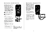
Page 9: ...vely to be precise the bar graph is used to display the time rest to accomplish the measurement 2 In order to obtain an accurate reading a capacitor must be discharged before measurement begins The meter has a built in discharge mode to automatically discharge the capacitor In discharge mode the LCD displays DIS C 3 Discharging through the chip is quite slow We recommend the user to discharge the ...

Page 10: ...e power source Connect The Red probe to the side of the circuit closest to the power source The Black probe to the side of the circuit to ground Turn the power ON and test Meter Functions Temperature 0 C 0 F IMPORTANT To avoid heat damage to the meter keep it away from sources of very high temperature The life of the Temperature Probe is also reduced when subjected to very high temperatures Probe ...

Page 11: ... lead in V Ω RPM terminal Connect the Black test probe to ground Connect the Red test probe to the signal out wire of the sensor to be tested Meter Functions Dwell Select the DWELL function with the rotary switch Insert Black lead in COM terminal Red lead in V Ω RPM terminal Connect the Black test probe to ground Connect the Red test probe to the wire that connects to the breaker points see illust...

Page 12: ...ms PULSE Pulse Width ms PERIOD Period Pulse Width is the length of time an actuator is energized For example fuel injectors are activated by an electronic pulse from the Engine Control Module ECM This pulse generates a magnetic field that pulls the injectors nozzle valve open The pulse ends and the injector nozzle is closed This open to close time is the Pulse Width and is measured in milliseconds...

Page 13: ...tary switch OR Select the 10RPM range with the rotary switch 1 000 to 12 000 RPM Multiply the displayed reading by ten to get actual RPM Press STROKE DIS button to select through RPM for 4 stroke RPM for 2 stroke and DIS ignitions Insert the inductive pickup connecting terminal into the meter Black lead in COM terminal Red lead in V Ω RPM terminal Connect the inductive pickup to a spark plug wire ...

Page 14: ...lity The probe is compatible with all DC millivolt measuring instruments or this automotive meter Infrared Temperature 0 C 0 F ranges measuring instruments that have a minimum of 1 MΩ input impedance and accept safety shrouded standard diameter 0 16 in 4 mm banana plugs Field of View The meter s field of view is 8 1 meaning that if the meter is 8 inches from the target the diameter of the object u...

Page 15: ...rared Temperature Probe OFF the DMM display will show 0 C or 0 F or 0mV The temperature scale can be changed to C or F by removing the battery from the battery compartment and moving the internal C F switch to the desired position If the test instrument displays an overload condition switch the DMM range from mV dc to V dc Increasing the range to V dc moves the decimal position three places to the...

Page 16: ...nt complies with IEC 1010 1 EN61010 1 Insulation Class2 Double insulation Overvoltage category CATIII1000V CATIV600V Display 4000 counts LCD display with function indication Polarity Automatic negative polarity indication Overrange OL mark indication Low battery indication The BAT is displayed when the battery voltage drops below the operating level Measurement rate 2 times per second nominal Auto...

Page 17: ... Range Resolution Accuracy 400 0mV 0 1mV 1 5 of rdg 5 dgts 4 000V 1mV 1 0 of rdg 3 dgts 40 00V 10mV 1 5 of rdg 3 dgts 400 0V 100mV 600V 1V 2 0 of rdg 4 dgts Input Impedance 10MΩ Frequency Range 50 to 60Hz DC Current Range Resolution Accuracy 40 00mA 10uA 1 5 of rdg 3 dgts 400 0mA 100uA 20A 10mA 2 5 of rdg 5 dgts Overload Protection 0 5A 250V and 20A 250V Fuse Maximum Input 400mA dc or 400mA ac rms...

Page 18: ...y 30oC 1000oC 1 oC 3 of rdg 5 oC 8 oF Meter only probe accuracy not included 22 oF 1832 oF 1oF Sensor Type K Thermocouple Diode Test Test current Resolution Accuracy 1 0mA typical 1 mV 5 of rdg 15 dgts Open circuit voltage 3 0V dc typical Audible continuity Audible threshold Less than35Ω Test current 1mA dc typical Maintenance REPLACING THE BATTERY WARNING To avoid electric shock disconnect the te...

Page 19: ...nnect the test leads from the meter and any item under test 2 Open the fuse door by loosening the screws on the rear cover using a Phillips head screwdriver 3 Remove the old fuse from its holder by gently pulling it out 3 Install the new fuse into the holder 4 Always use a fuse of the proper size and value 0 5A 250V φ5 x 20 fast blow for the 400mA range 20A 250V φ6 3 x 32 fast blow for the 20A ran...

Reviews: