background image

6

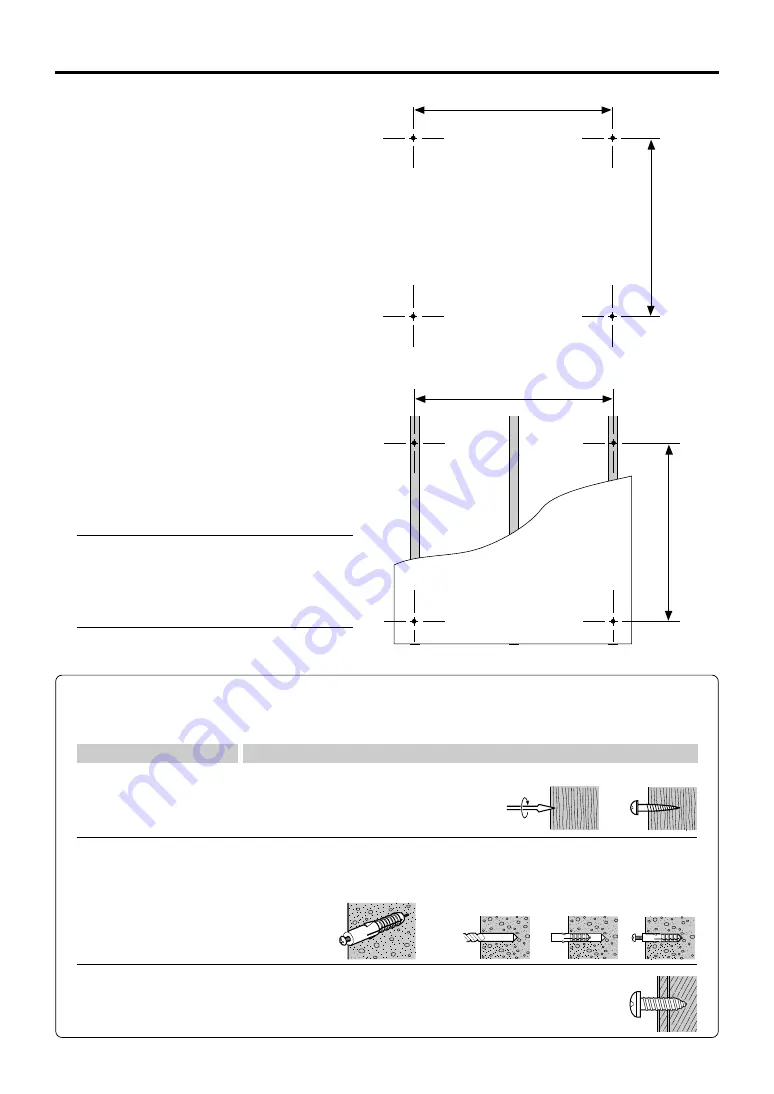
1200mm

1077mm

1200mm

1077mm

(1) Determining the installation location

The diagram indicates the dimensions of the installa-
tion positions. The installation position is the same for
both the standard type and the wide type.

The installation of the Copyboard to the wall is per-
formed after the printer tray is assembled and attached
to the Copyboard. See Page 9.

• When the Wall Is Concrete

Embed the commercially available anchor bolts or
anchor nuts for M6 at the installation positions. (See
below)

• When the Wall Structure Is Plywood or

Plaster Board, etc.

Please check that a post or stud is located at the
installation position indicated by the dimensions.
When a post is not located at the target installation
position, please use a wall support fitting that is
available separately. Attach a wall support fitting to
the post or stud.

Note

• When the building does not have posts, please use the

stand.

• Separate optional items are available when the standard

wall mounting is not possible, or when installation will be
made to a partition.

5. WALL MOUNTING

Stud, etc.

Reference: Installation Method for Various Wall Materials

Please perform an installation that suits the wall material.
Please install the Copyboard to posts or studs when the wall surface is of insufficient strength.

Wooden Walls

Wood screws

 Make a suitable hole with an auger and 

attach the Copyboard with wood screws.

Concrete Walls

Anchors

 Make a base hole in the wall with a drill. 

 Insert the anchor. 

 Fasten the Copyboard

with screws.
Please use a drill of the hole diameter specified for the anchor.

Steel Walls

Phillips head tapping screws (Pan head)

Check that the steel wall is reinforced and use a drill a hole of suitable
diameter, then attach the Copyboard with tapping screws.

Installation Wall Material

Installation Method

Summary of Contents for M-10 Series

Page 1: ...nterest of the safety of the customer please perform installation work paying due attention to the strength of the installation location to ensure that it can bear the load of the Copyboard printer an...

Page 2: ...ting positions of the Copyboard are not reached please use optional wall support fittings Please use hardware like anchor nuts and anchor bolts for mounting on a concrete wall 1 PACKAGING LIST Please...

Page 3: ...print See Page 12 When mounting to a wall Please consult with a dealer or installation tradesman Installation work should not be done by the customer The installation method will change depending on...

Page 4: ...he printer tray is not required when the Copyboard is used only for memory storage 5 Place the stand s hooks in the mount ing holes in the support fittings and insert the grooves in the hooks se curel...

Page 5: ...e printer tray and pipe Pushing the main unit back towards the stand insert the groove in the stay into the printer tray Note Check again that the grooves in the stand s hooks are securely inserted in...

Page 6: ...ll support fitting to the post or stud Note When the building does not have posts please use the stand Separate optional items are available when the standard wall mounting is not possible or when ins...

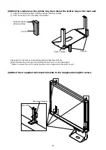
Page 7: ...ions adhesive surfaces Stick the cushions 2 on the back of the bracket Cushions Back of bracket Protective sheet on adhesive surface Cushion Wall mount bracket M4 screw See page 9 for instructions on...

Page 8: ...anchoring the Copyboard to a wall or wall support fitting The anchoring method will differ depending on the wall mounting method Installing on a Concrete Wall Anchor nut etc M6 screw Mounting to a Po...

Page 9: ...asten the printer tray to the brackets with six M3 screws Printer tray M3 screw Should the printer touch on the wall sur face attach the printer tray forward M4 screws Front screw hole Front screw hol...

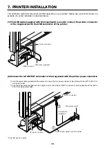
Page 10: ...able supplied with the Copyboard is used to connect the printer connector of the Copyboard with the USB connector of the printer 7 PRINTER INSTALLATION 2 Connect the AC OUTPUT connector of the Copyboa...

Page 11: ...onnectors are securely fastened 1 Remove the backing paper from the rear surface of the clip and affix the clip at the desired loca tion 2 Raise the band of the clip dis engage it from the hook and pu...

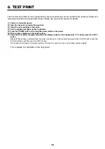
Page 12: ...5 Press the POWER button of the Copyboard and switch on the power 6 Write or draw a diagram on the sheet surface 7 Check that the number of copies indicated in the display window of the Copyboard is...

Page 13: ...of the power cable at the wall AC outlet Remove the rear plate fitting on the back of the copyboard Removal of the 3 screws will release the fittings WARNING When replacing the fluorescent lamp be cer...

Page 14: ...he hole position of the Copyboard rear frame The Copyboard will disengage from the hooks when it is lifted up about 1 cm Fully hook the 2 left and right installation holes of the copyboard rear frame...

Page 15: ...14 2097 03B 2003...
Reviews: