010219/0 ControlPro/Diluter
EN - 13
Symptom
Problem
Possible
cause
Solution
Fillter
pressure
value is
negative or
illogical
Wrong
pressure
indication
One pneumatic
hose is loose
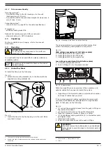
Connect the hose
Inverted
connection of
the pneumatic
hoses (+ vs. –)
Correct the
connection (refer to
par. 4.5.1)
Wrong type of
external
pressure sensor
configured
(PT-1000 vs.
PT-2500)
Set the correct type
of pressure sensor
(refer to screen
1.2)
Malfunction of
frequency
inverter
Fan pressure
value is
negative
Wrong
connection of
the pneumatic
hose (+ vs. –)
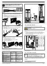
Correct the
connection (refer to
par. 4.5.2)
USB stick is
not
recognized
Firmware
update not
possible
USB-stick does
not comply with
USB 2.0
standard (too
slow)
Use a USB 2.0 or
USB 3.0 stick
9
SPARE PARTS
The following spare parts are available for the product.
9.1
ControlPro/Panel
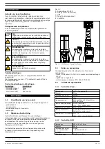
Refer to exploded view Fig. III on page 36.
Article no.
Description
0000103139
Switch mode power supply 24V DC 2.5A
0000113558
Indicator light yellow 24V
0000113559
PCB main board ControlPro
0324000300
Indicator light white 24V
0324000310
Indicator light green 24V
0324000320
Indicator light red 24V
0360000060
Buzzer
9.2
ControlPro/HMI
Refer to exploded view Fig. IV on page 36.
Article no.
Description
0000112777
ControlPro/HMI (complete)
0000113560
Dust cap for ControlPro/HMI
10
ELECTRICAL DIAGRAM
Refer to the separately supplied electrical diagram.
11
DISPOSAL
After life of the product, dispose it of in accordance with
federal, state or local regulations.
CE DECLARATION
CE Declaration of Conformity for machinery
We, Plymovent Manufacturing B.V., Koraalstraat 9, 1812 RK
Alkmaar, the Netherlands, herewith declare, on our own
responsibility, that the product:
- ControlPro/Diluter
which this declaration refers to, is in accordance with the
conditions of the following:
Directives:
- EMC 2014/30 EU | EMC Directive
- LVD 2014/35 EU | Low Voltage Directive
Harmonised Standards:
- EN-IEC 60204-1:2006 | Safety of machinery - Electrical
equipment of machines - Part 1: General requirements
- EN-IEC 61439-1:2011 | Low-voltage switchgear and
controlgear assemblies - Part 1: General rules
- EN-IEC 61131-2:2007 | Programmable controllers - Part 2:
Equipment requirements and tests
- EN-IEC 61000-6-2:2005 | Electromagnetic compatibility
(EMC) - Part 6-2: Generic standards - Immunity for industrial
environments
- EN-IEC 61000-6-4:2007 | Electromagnetic compatibility
(EMC) - Part 6-4: Generic standards - Emission standard for
industrial environments
Alkmaar, Netherlands, 1 March 2019
Jeroen Crezee
Manager R&D
An
installation
is defined as a combination of several finished products
or components that are assembled by an installer at a given place. The
various parts of the installation are intended to operate together in a
particular environment and to perform a specific task. The entire
installation must comply with the relevant directives and standards. The
assembly instructions given by the manufacturer, as well as the whole
method of installation, must be in accordance with good engineering
practices within the context of installations, as well as installation rules.
Considering the above, the installer will be responsible for completing
the installation and issuing the final CE Declaration of Conformity.

