010219/0 ControlPro/Diluter
EN - 7
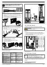
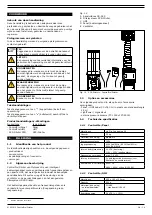
General instructions to connect a cable to a
certain connector
(unless otherwise stated)
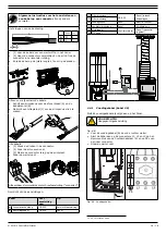
Wire stripping:
A
B
mm in.
A
50
2
B
6
¼
• (1) Put the cable through a cable gland M16 into the
Panel.
• (2) Carefully remove the connector from the PC board.
Pull the connector in a
horizontal
direction.
• Cut the cable to the correct length and strip the wires.
2
1
5
3
4
Shielded cables only:
• Put a shrink tube on the drain wire (A) and the cable
jacket (B).
• Use a heat gun (C) to tighten the shrink tube.
C
A
B
C
A
B
All cables:
• (3) Put the wires into the connector.
• (4) Tighten the screws.
• (5) Put the connector back on the PC board.
• Tighten the cable gland.
2
1
5
3
4
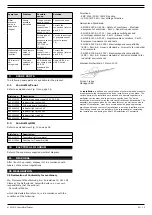
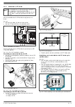
Detachable screw terminal block (“connector”)
Overview of connections:
Cable
For connection
of:
To:
A
Pneumatic hose
CB-SCS
Compressed air
supply
B
Control cable
CB-SCS
Panel
C
Filter pressure tube (+)
CB-SCS
Panel (push-in
fittings)
D
Filter pressure tube (–)
E
Mains cord
Panel
Mains
F
Fan pressure tube (+)
Panel
Vertical duct
G
Motor cable
Fan motor
Panel (frequency
inverter)
H
PTC cable
B C
D
E
A
A
B
C
D
E
F
G
H
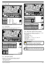
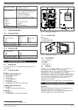
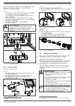
4.4.1 Mains cord (cable #5)
To install the mains cord to the Panel, do the following.
CAUTION
High voltage connection
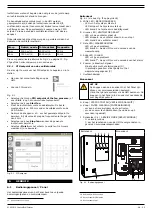
• Put the mains cord (B) through the right cable gland.
• Connect it to connectors L1, L2 and L3 on the terminals of
the main switch (A) and to PE
10
on the left connector.
• Fasten the cable gland.
A
B
PE
Fig. 4.8 Mains cord
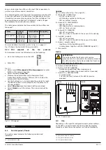
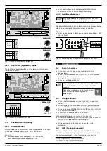
4.4.2 Motor cable + PTC cable
The motor cable and the PTC cable are supplied in
the SCS-Diluter PRO package;
- motor cable: 4-cored shielded cable 4 mm²
- PTC cable: 2-cored shielded cable 0,75 mm²
To install the motor cable and PTC cable to the Panel, do the
following.
10. PE = Protective Earth

