background image

0000110291/011222/B MiniMan-75 

6

6.2 

Arm adjustment

If the extraction arm, or a part of it, does not stay in the 

desired position, you must adjust the friction.

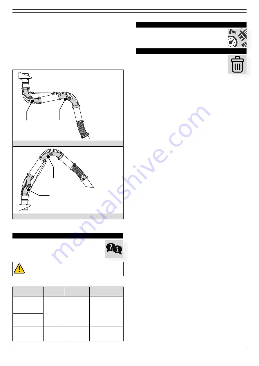
Fig. 6.1

•  Determine which part of the arm needs more or less 

friction;


- inner tube (ref. Fig. 2.1E): adjust friction joint A


- outer tube (ref. Fig. 2.1F): adjust friction joint B

A

A

B

B

MiniMan 

H

A

A

B

B

MiniMan 

S

Fig. 6.1  Adjustment points

TROUBLESHOOTING

If the product does not function (correctly), consult 

the checklist below to see if you can remedy the 

error yourself. Should this not be possible, contact 

your supplier.

WARNING!

Obey the safety regulations that are written in

chapter 3 when you carry out the activities below.

Symptom

Problem

Possible 

cause

Solution

The extraction 

arm does not stay 

in the desired 

position

Escape of 

fume or 

dust; no 

proper 

extraction

Friction 

setting is not 

correct

Adjust the friction; 

refer to § 6.2

You cannot get 

the arm in the 

desired position
Escape of fume or 

dust; insufficient 

extraction

No proper 

extraction

Loose hose(s) Fasten the hose(s) 

properly

Hose damage Replace the hose(s)

SPARE PARTS

The following spare parts are available for the 

product;


refer to exploded view Fig. V on page 9 

DISPOSAL

After life of the product, dispose of it in accordance 

with federal, state or local regulations.

Summary of Contents for MINIMAN-75

Page 1: ...www plymovent com Extraction arm MINIMAN 75 Installation and user manual EN...

Page 2: ...use maintenance and repair of the product mentioned on the cover page of this document This publication is to be used for the standard model of the product of the type given on the cover page Thus the...

Page 3: ...ption The MiniMan 75 is a compact flexible arm which is ideal for all types of smaller dust and fume applications The arm is fitted with exterior friction joints ClearThru design which allows for maxi...

Page 4: ...hould instruct the personnel in accordance with the manual and observe all instructions and directions given Do not change the order of the steps to perform Keep the manual with the product Users The...

Page 5: ...eck it for damage Verify the functioning of the safety features During use always use Personal Protective Equipment PPE to avoid injury This also applies for persons who enter the work area Check the...

Page 6: ...working position changes move the nozzle to the correct position in relation to the workpiece Turn off the connected extraction fan or system approx 20 seconds after finishing the work A B A C B A C...

Page 7: ...ible contact your supplier WARNING Obey the safety regulations that are written in chapter 3 when you carry out the activities below Symptom Problem Possible cause Solution The extraction arm does not...

Page 8: ...00 mm 3 ft C D E 1500 mm 5 ft MM 75 1 0 H MM 75 1 5 H mm inch mm inch A 1160 46 B 1512 60 C 2250 89 2500 98 Height from the floor D 1500 59 1500 59 E 750 30 250 10 Fig II Pressure drop 0 100 200 300 4...

Page 9: ...t 1000 mm 3 ft 1500 mm 5 ft 1000 mm 3 ft MM 75 1 0 H MM 75 1 5 H MM 75 1 0 H PA 110 160 1000 mm 3 ft MM 75 1 0 H PA 220 160 Fig IV Mounting examples MiniMan S A B 1500 mm 5 ft 1500 mm 5 ft 1000 mm 3 f...

Page 10: ...0000101985 0000101986 0000101983 0000101984 0000102799 0000102800 0000102803 0000102804 0000102801 0000102802 0000102805 0000102806 0000102801 0000102802 0000102805 0000102806 0000102799 0000102800 00...

Page 11: ...MM 75 white MM 75 1 0 H 0000101987 Balancing strap MM 75 1 0 H 0000102799 Inner tube MM 75 1 0 white 0000102800 Inner tube MM 75 1 0 yellow 0000102801 Outer tube MM 75 1 0 white 0000102802 Outer tube...

Page 12: ...www plymovent com 0000110291 011222 B MiniMan 75...

Reviews: