0507347110/160114/B SHIELD fire safety solutions (5k1)
| INSTALLATION | EN - 6
ENGLISH
4.1
MDB filter system
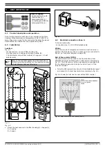
Before installing the components of SHIELD fire safety
solutions, make sure the Cart-D filter cartridges of the
connected MDB filter system are properly installed. To check
this, refer to the corresponding manual.
•
Securely check the installation of the Cart-D filter cartridges.
4.2
Tools and requirements
- connection wire: 5 x 20 AWG
- connection wire: 5 x 20 AWG shielded cable
- electric drill
- self-tapping screws
- mounting material ShieldControl 5k1
- metal cable glands
- duct support material (depending on weight of sliding valves)
- lifting and climbing gear
- existing duct: angle grinder or jigsaw
4.3
Installation and commissioning
To avoid accidental fire alarms and the activation of FlameShield
fire extinguishing generators, the following installation and
commissioning sequence should be followed. Deviation from
this sequence is allowed, provided the FlameShield module(s)
is/are always the last to be connected, even after having
performed the functional tests.
1. Filter/fan installation
2. System control panel SCP
3. ShieldControl panel (
without power
)
4. Detectors (heat, sparks, smoke)
5. Valves (sliding solenoid valve)
6. FlameShield fire extinguishing generators (
isolated
)
•
Refer to chapter 13 for extensive commissioning checklist.
4.4
Functional test
To perform any functional test, the following instructions should
be followed.
•
Ensure that the FlameShield module(s) is/are isolated.
•
Perform detector test. Sound alarm will go off.
•
Check fire zone (
FIRE IN ZONE
).
•
Press the
SIGNAL SILENCE
button on the ShieldControl panel to
suppress alarm.
•
Press the
SYSTEM RESET
button.
To proceed with testing:
•
Restart procedure.
If testing has been completed:
•
Reconnect the FlameShield module(s).
•
Make sure the panel is in
RUN
mode.
5.1
Product description and operation
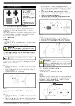
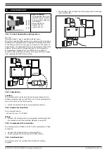
ShieldControl 5k1 is a fire detection panel
1
with a separate
manual call point. It has three detection zones all of which are
capable of activating the FlameShield fire extinguishing
generators.
The fire detection panel makes it possible to connect additional
manual call points.
ShieldControl has two back-up batteries to allow for continuous
operation in the event of power failure.
5.2
Installation
To be sourced locally:
- connection wire: 5 x 20 AWG shielded cable
- mounting material
- metal cable glands
Location
- on the wall or at a convenient location close to the filter
installation
- at eye level
- indoors
Ambient conditions
- Min. temperature: –5°C (23°F)
- Max. temperature: +40°C (104°F)
- Relative humidity: max. 95%
The ShieldControl housing is NEMA 1 rated. It must be shielded
from excessive dust, welding sparks and grinding sparks, if any,
by e.g. an enclosure.
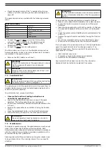
Installation
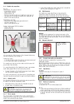
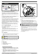
To install the ShieldControl panel, proceed as follows.
•
Mount the ShieldControl panel at all four mounting points.
Use suitable fixtures so that the panel cannot move after it
has been installed.
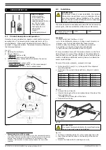
5.3
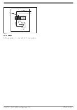
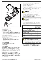
Fire alarm sounder
Installation, tone selection and volume control of the fire alarm
sounder are described in the installation manual supplied with
the product.
•
Mount the fire alarm sounder at an appropriate position.
•
Select the desired tone.
•
Adjust the noise to the desired level.
4
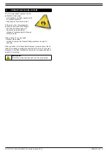
INSTALLATION (GENERAL)
WARNING!
Improper installation of the Cart-D filter cartridges will
cause internal leakage and a reduced filter efficiency.
In combination with SHIELD fire safety solutions it can
lead to a false fire alarm.
5
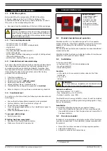
SHIELDCONTROL 5K1
Scope of supply:
- fire detection panel
- battery pack (2)
- fire alarm sounder
- manual call point
- EOL resistor-diode
- detonation simulator
- key (2)
1. UL Standard 862
WARNING
To prevent damage, do
not
mount the ShieldControl
panel close to sources of excessive heat.


