0507291010/260411/A T-Flex/CW
EN - 11
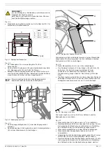
•
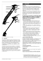
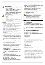
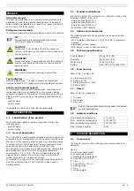
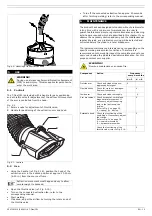
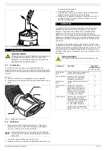
Mount the wall mounting bracket to the wall. Refer to section
4.1 for recommended installation height.
Fig. 4.1: Mounting of wall mounting bracket
•
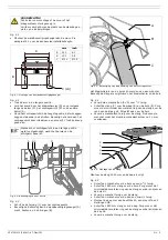
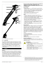
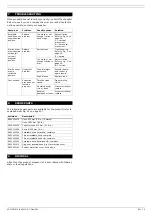
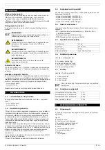
Pull the arm in the longest position.
•
Guide the rope through the rotating hinge (D) and
subsequently over the reel (C), the counterweight (B) and
the other reel (A).
•
Keep the counterweight in the highest position, which means
just below the reels. Securely fasten the rope to the
counterweight by tying a knot (E).
Fig. 4.2: Attachment of rope
•
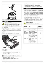
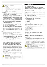
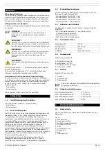
Slide the counterweight casing (C) over the counterweight.
•
Fasten the casing to the wall mouting bracket (A) using 2
bolts M8x10 + 2 washers M8 (B).
Fig. 4.3: Mounting of counterweight casing
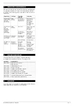
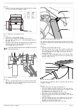
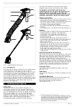
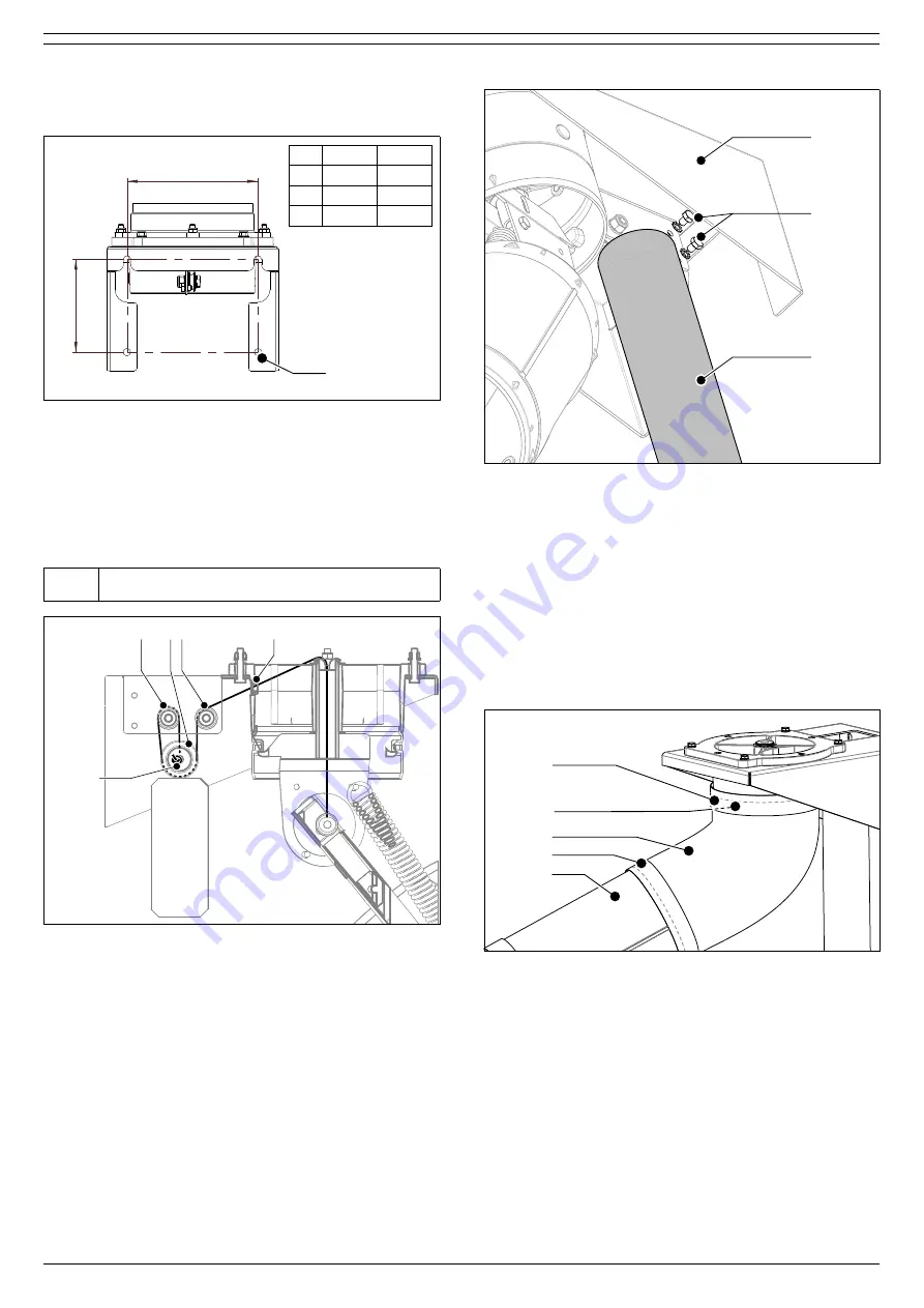
The rotating hinge and the tube are both provided with a bush.
To fix the hose between the rotating hinge and the tube, proceed
as follows.
•
Fold back
2
/
3
of both bushes (A+D).
•
Place the flexible hose (C) over the collar (B) and the tube
(E). To secure the hose, at least one metal ring of the hose
should be applied over the ridges of the collar. The same
goes for the tube.
•
Fold back the bushes and place them over the hose. Make
sure the upper bush overlaps the aluminium rotating hinge
approx. 10 mm (0.4 in.).
Fig. 4.4: Mounting of the hose
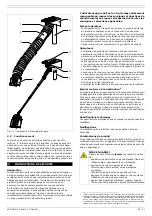
To mount the hose 1650 mm (65 in.) and the extraction hood,
proceed as follows.
•
Place a bush over the tube and fold back
2
/
3
.
•
Place the flexible hose 1650 mm (65 in.) over the tube. To
secure the hose, at least one metal ring of the hose should
be applied over the ridges of the tube.
•
Fold back the bush and place it over the hose.
•
Place a bush over the extraction hood and fold back
2
/
3
.
•
Mount the extraction hood using a bolt M6x40, a nut M6 and
2 washers M6.
•
Place the flexible hose over the extraction hood. To secure
the hose, at least one metal ring of the hose should be
applied over the ridges of the hood.
•
Fold back the bush and place it over the hose.
Tying the counterweight too low will affect the reach of
the extraction arm.
A
B
C (x4)
mm
inch
A
210
8.3
B
150
5.9
C
Ø 12
Ø 0.5
A B C
D
E
B
C
A
A
B
C
D
E

