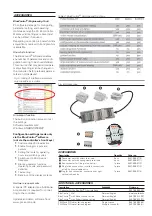
with Modbus RTU protocol that is fit-
ted into the top-hat DIN rail.
Devices with option system interface
can be connected via bus coupler to
fieldbusses.
Password protection
If required, unauthorized access to the
various Operating Levels can be pre-
vented with a password, or an entire
level can be blocked.
TECHNICAL DATA
INPUTS
Survey of inputs
Input
Purpose
INP1
As INP2 default;
X1 (process value 1), universal input
INP2
(mA DC)
External setpoint, process value X1;
Input for additional limit monitoring
and display
INP2
(mA AC)
(option)
External setpoint, heating current;
Process value X1; Input for additional
limit monitoring and display
INP2
(universal)
(option)
X2 (process value 2), universal input,
external setpoint, Process value X1;
Input for additional limit monitoring
and display
di1
Operation disabled; Reset of stored
alarms; Switchover to 2nd setpoint
SP.2, external setpoint, fixed output
value Y.2, manual operation, controller
‘off’, 2nd process value.
UNIVERSAL INPUT INP1
Resolution:
>14 bits
Decimal point:
0 to 3 decimals
Digital input filter:
adjustable 0.0...999.9 s
Scanning cycle:
100 ms
Linearization:
15 segments, adaptable with
BlueControl
®
Measurement value correction:
2-point or offset
Type:
single-ended (except for thermocouples)
Thermocouples (Table 1)
Input resistance:
≥
1 M
Ω
Influence of source resistance:
1 µV/
Ω
Input circuit monitor:
sensor break, polarity
Cold-junction compensation
•
Internal
- additional error: typical
ß_
0.5 K
max.
ß
+1.2 K
•
External:
0 ...100 °C
Break monitoring
Sensor current:
ß
1 µA
Operating sense configurable
Resistance thermometer (Table 2)
Connection technique:
3-wire or
4-wire
(not available if using INP2)
Lead resistance:
max. 30
Ω
(for max. end of span)
Input circuit monitoring:
break and short circuit
Measurement span
Separated into ranges
Physical measurement range:
0...4,500
Ω
The BlueControl
®
software enables
the internal characteristic curve for the
KTY 11-6 temperature sensor to be
adapted.
Current and voltage measurement
(Table 3)
Span start and span:
anywhere within the
measurement range
Scaling:
freely selectable, –1,999...9,999
Input circuit
12.5% below span
monitoring (current):
start (2 mA)
2
KS 45
Thermocouple type
Measurement range
Error
Typical resol.(
∅
)
L
Fe-CuNi (DIN)
-100...900°C
-148...1,652°F
ß
2K
0.1 K
J
Fe-CuNi
-100...1,200°C
-148...2,192°F
ß
2K
0.1 K
K
NiCr-Ni
-100...1,350°C
-148...2,462°F
ß
2K
0.2 K
N
Nicrosil/Nisil
-100...1,300°C
-148...2,372°F
ß
2K
0.2 K
S
PtRh-Pt 10%
0...1,760°C
32...3,200°F
ß
2K
0.2 K
R
PtRh-Pt 13%
0...1,760°C
32...3,200°F
ß
2K
0.2 K
T**
Cu-CuNi
-200...400°C
-328...752°F
ß
2K
0.05 K
C
W5%Re-W26%Re
0...2,315°C
32...4,199°F
ß
3K
0.4 K
D
W3%Re-W25%Re
0...2,315°C
32...4,199°F
ß
3K
0.4 K
E
NiCr-CuNi
-100...1,000°C
-148...1,832°F
ß
2K
0.1 K
B*
PtRh-Pt6%
0(400)...1,820°C
32(752)...3,308°F
ß
3K
0.3 K
Special
-25 … 75 mV
ß
0.1%
0.01%
* Values apply from 400°C upwards.
**Values apply from -80°C upwards.
Table 1: Thermocouple input
Type
Sensor current
Measurement range
Error
Typical resol. (
∅
)
Pt100***
≤
0,25 mA
-200..100(150)°C
-328...212(302)°F
ß
1 K
0.1 K
Pt100
-200...850°C
-328...1,562°F
ß
1 K
0.1 K
Pt1000
-200...850°C
-328...1,562°F
ß
2 K
0.1 K
KTY 11-6*
-50...150°C
-58...302°F
ß
2 K
0.1 K
Special*
0...4,500
[
**
ß
0.1%
0.01%
Special*
0...450
[
**
ß
0.1%
0.01%
Poti
0...160
[
**
ß
0.1%
0.01%
Poti
0...450
[
**
ß
0.1%
0.01%
Poti
0...1,600
[
**
ß
0.1%
0.01%
Poti
0...4,500
[
**
ß
0.1%
0.01%
* Default setting is the characteristic for KTY 11-6 (-50...150°C)
** Including lead resistance
*** up to 150°C at reduced lead resistance (max. 160
[
)
Table 2: Resistive inputs
Measurement range
Input resistance
Error
Typical resol.(
∅
)
0...10 Volt
≈
110 k
[
ß
0.1 %
0.6 mV
-10...10 Volt
≈
110 k
[
ß
0.1 %
1.2 mV
-5...5 Volt
≈
110 k
[
ß
0.1 %
0.6 mV
-2,5...115mV*
> 1 M
[
ß
0.1 %
6
µ
V
-25...1150mV*
> 1 M
[
ß
0.1 %
60
µ
V
-25...90mV*
> 1 M
[
ß
0.1 %
8
µ
V
-500...500mV*
> 1 M
[
ß
0.1 %
80
µ
V
-200...200mV*
> 1 M
[
ß
0.1 %
40
µ
V
0-20 mA
20
Ω
ß
0.1 %
1.5
µ
A
* For INP1: high-impedance, without break monitoring
for INP2: high impedance, break monitoring always active
Table 3: Current and voltage input

