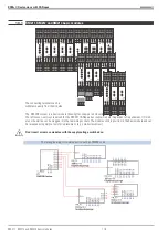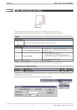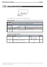
19.6
Potentiometer connection and calibration
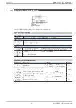
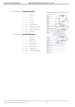
Connection:
Modules RM 222-1 and RM222-2 are also suitable for connection of
potentiometers. Max. two potentiometers can be connected to module
RM222-2 and max. four potentiometers can be connected to module
RM 222-1.
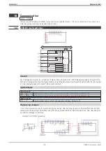
For potentiometer measurement, a voltage divider circuit is used. The
channels designed for voltage can be changed for potentiometer mea-
surement pairwisely (by means of jumpers on the module circuit
board)
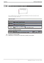
Uconst: Us = 5V DC (output instead of +24V OUT);
Short circuit proof current limiting: 20mA
Max. load: 4mA/channel;
]
I
ß
20mA (can be
distributed
to the 4
module channels.
The min. resistance values must be
4 x 1000
[
, 2 x 500
[
or 1 x 250
[
Calibration:
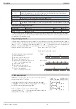
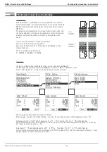
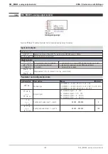
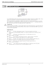
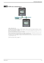
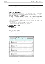
In order to calibrate the potentiometer inputs, call up menu item
Calibration.
For this, leave the operating menu, call up
Main menu
r
Miscellaneous,
s
elect
Calibration
, and call up the module you wish to calibrate.
Start by selecting the channel you wish to calibrate.
Press key
I
to select the channel number (
chnl.1
) and change it after acknowledgement via key
M
Subsequently, press
Quit
and change over to
Set 0%
. Press key
M
.
Set 0%
starts flashing.
Bring the resistance value into the position for X0. The value valid for this channel appears on display
X.
Press key
M
again to store this value as
X0.
Actuate
Set 0%
and change over to
Set 100%.
Press key
M
.
Set 100%
starts flashing.
Now, bring the resistance value into the position for X100. The value valid for this channel appears on display
X
. Press
key
M
again to store this actual value as X100.
KS98+ I/O extensions with CANopen
Potentiometer connection and calibration
Potentiometer connection and calibration
124
1
2
3
5V
U 1
4
5
6
5V
U2
7
8
9
5V
U 3
10
11
12
5V
U4
only
RM222-1
RM222-1
RM222-2
Summary of Contents for KS 98
Page 8: ...Description 9499 040 50611 Construction 8...
Page 10: ...Important technical data 9499 040 50611 Further external in and outputs 10...
Page 12: ...Versions 9499 040 50611 I O modules for units with modular option c basic card 12...
Page 14: ...Front view 9499 040 50611 14...
Page 16: ...Mounting 9499 040 50611 16...
Page 26: ...Maintenance 9499 040 50611 Further information 26...
Page 36: ...Scaling and calculating functions 9499 040 50611 LG10 10s logarithm 36...
Page 74: ...Signal converters 9499 040 50611 MEAN mean value formation 74...
Page 128: ...KS98 I O extensions with CANopen 9499 040 50611 RM_DMS strain gauge module 128...
Page 132: ...CSEND Send mod blockno s 21 23 25 27 No 57 132...
Page 140: ...Description of KS98 CAN bus extension 9499 040 50611 140...
Page 202: ...Controller 9499 040 50611 Process value calculation 202...

