6
Electrical connections
6.1
Safety hints
a
Following the enclosed safety hints 9499 047 07101 is indispensable! The instrument insulation meets standard
EN 61 010-1 (VDE 0411-1) with contamination degree 2, overvoltage category III, operating voltage range 300 V
and protection class I.
a
With horizontal installation, the following rule is applicable additionally: with the instrument module
withdrawn, a facility which prevents conducting parts from dropping into the open housing must be provided.
a
If the unit is switched to off-line, the outputs keep the status from the time of switch-over!!!
6.2
Electromagnetic compatibility
The unit meets European guideline 89/336/EEC. The following European generic standards are met:
Electromagnetic radiation: EN 50081-2
and
Electromagnetic immunity: EN 50082-2
. The unit is suitable for use in indus-
trial areas (in residential areas, RF interference may occur). The electromagnetic radiation can be reduced decisively by
installing the unit in a grounded metal switch cabinet.
6.3
Measurement earth (for grounding interference)
a
Interference voltages, e.g. high-frequency interference, acting on the unit from outside may cause functional
trouble. For grounding the interference voltages and ensuring interference suppression, a measurement earth
must be connected.
Terminal A11 must be connected to ground potential by means of a short cable (approx. 20 cm, e.g. at control
cabinet ground)!
This cable must be kept separate from power supply cables. On instruments with current outputs at OUT1 and
OUT2 proceed accordingly with terminal P13.
6.4
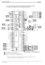
Connecting diagram
w
Power supply cables must be kept
separate
from signal and measuring cables.
w
We recommend using
twisted and screened measuring cables
(screening connected to measurement earth).
w
Connected motor actuators must be provided with
protective circuitry
to manufacturer specifications. This
avoids high voltage peaks, which may cause trouble to the instrument.
w
The units must be protected with a fuse individually per unit or in common according to a max. power
consumption of 10 VA (standard fuse ratings, min. 1 A)!
9499 040 50611
Electrical connections
17
Safety hints
Summary of Contents for KS 98
Page 8: ...Description 9499 040 50611 Construction 8...
Page 10: ...Important technical data 9499 040 50611 Further external in and outputs 10...
Page 12: ...Versions 9499 040 50611 I O modules for units with modular option c basic card 12...
Page 14: ...Front view 9499 040 50611 14...
Page 16: ...Mounting 9499 040 50611 16...
Page 26: ...Maintenance 9499 040 50611 Further information 26...
Page 36: ...Scaling and calculating functions 9499 040 50611 LG10 10s logarithm 36...
Page 74: ...Signal converters 9499 040 50611 MEAN mean value formation 74...
Page 128: ...KS98 I O extensions with CANopen 9499 040 50611 RM_DMS strain gauge module 128...
Page 132: ...CSEND Send mod blockno s 21 23 25 27 No 57 132...
Page 140: ...Description of KS98 CAN bus extension 9499 040 50611 140...
Page 202: ...Controller 9499 040 50611 Process value calculation 202...

