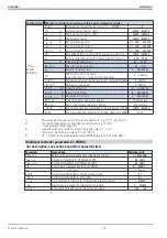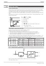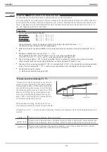
Three-point controller
Switching controller with
three
switching statuses:
1.
Heating
switched
on;
r
output
Y1 = 1
, Y2 = 0
2. Heating and cooling switched off;
r
outputs Y1 = 0, Y2 = 0
3.
Cooling
switched
on;
r
outputs Y1 = 0,
Y2 = 1
E.g. for temperature control with electrical heating (
h
)
and
cooling (
c
).
Adjust cycle time
Tp1
and
Tp2
as follows:
Tp
Tu
1
0 25
<=
·
,
(h)
Tp
Tu
2
0 25
<=
·
,
(c).
With higher
Tp1
/
Tp2
, oscillations have to be expected. Cycle times
Tp1
and
Tp2
are the minimum cycle times at
50% duty cycle.
Output Y1 (heating)
Output Y2 (cooling)
PD/PD action
(
Tn
= 0
=
switched off Tn =
Î
)
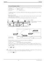
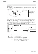
The positioning range reaches from 100 % heating (Y1) to 100 % cooling (Y2).
The proportional bands must be adapted to the various heating and cooling power values. In order to keep the control
variable constant, a defined amount of energy dependent of set-point is required. This causes a permanent control de-
viation, which increases with growing X
p(1,2).
DPID/DPID action
By means of the I action, line-out without permanent control deviation is possible.
Transition from trigger point 1 (heating) to trigger point 2 (cooling) is without neutral zone. The proportional bands must
be adapted to the various heating and cooling power values.
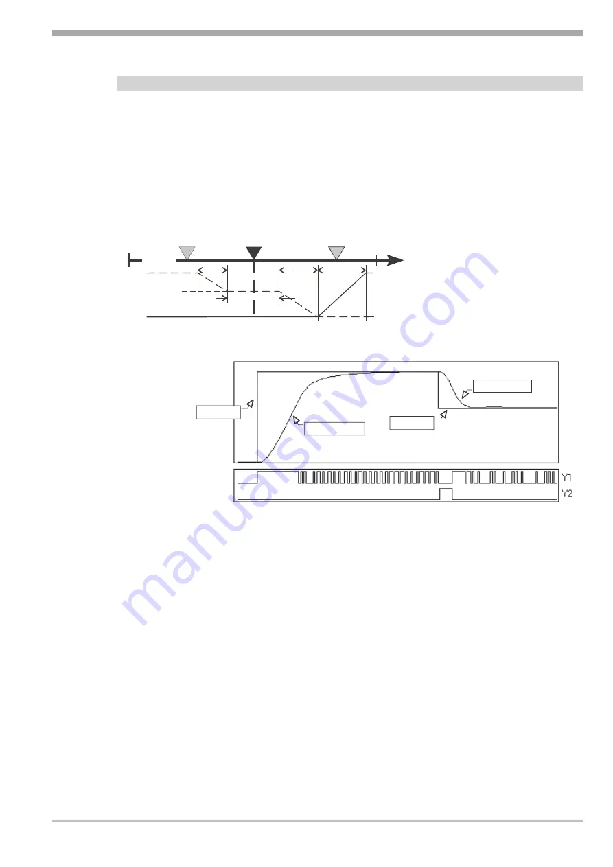
Fig.: 1 shows the static characteristic for inverse output action.
Direct/inverse switchover only causes exchanging of the outputs for “heating/cooling”.
Expressions “heating” and “cooling” may also mean similar processes (dosing acid/lye, ...).
The neutral zone is adjustable separately for the trigger points (X
sh1
, X
sh2
)
i.e. it need not be symmetrical to the
set-point.
The type of positioning signals is selectable:
CFunc
= 3-point heating switching,
cooling switching
CFunc
= cont/switchheating continuous,
cooling switching
CFunc
= switch/contheating switching,
cooling continuous
Combination “heating continuous” and “cooling continuous” is covered by “splitRange - continuous controller with
split-range behaviour”.
r
see also "continuous controller" page: 174.
9499 040 50611
Controller
171
Controller behaviour
100%
0%
100%
0%
Y1
Â
h
Y2
Â
c
Xn100
Xn0
W0
Weff
W100
Xeff
Xp2
Y0
Xp1
=Xp'+Xp''
Xp'
Xp''
Xsh1 Xsh2
Fig.: 1
Static operating principle
of a three-point controller
process value
Set-point.
Set-point.
process value
Summary of Contents for KS 98
Page 8: ...Description 9499 040 50611 Construction 8...
Page 10: ...Important technical data 9499 040 50611 Further external in and outputs 10...
Page 12: ...Versions 9499 040 50611 I O modules for units with modular option c basic card 12...
Page 14: ...Front view 9499 040 50611 14...
Page 16: ...Mounting 9499 040 50611 16...
Page 26: ...Maintenance 9499 040 50611 Further information 26...
Page 36: ...Scaling and calculating functions 9499 040 50611 LG10 10s logarithm 36...
Page 74: ...Signal converters 9499 040 50611 MEAN mean value formation 74...
Page 128: ...KS98 I O extensions with CANopen 9499 040 50611 RM_DMS strain gauge module 128...
Page 132: ...CSEND Send mod blockno s 21 23 25 27 No 57 132...
Page 140: ...Description of KS98 CAN bus extension 9499 040 50611 140...
Page 202: ...Controller 9499 040 50611 Process value calculation 202...


