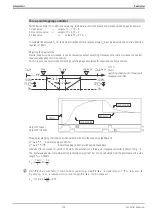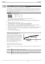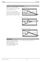
Start in manual mode or in automatic mode :
Basically, the PIDMA self-tuning algorithm does not distinguish between these two start conditions. In both cases, the
operator must ensure that the process conditions are stable. In automatic mode, however, the PIDMA works with the
non-optimized parameters until start of the correcting variable pulse. This means that, in the majority of cases, better
stability of process conditions, i.e. better self-tuning results, are possible in manual mode. When changing to manual
mode, the correcting variable output last is taken over as manual correcting variable and used during estimation.
After self-tuning start, the estimation timer for drift detection and noise detection is started at first. In the second
phase, the correcting variable is changed by correcting variable step change
dYOpt
. When the process value has
changed by more than Xlimit, the correcting variable is reset to the original value. In the third phase, the PIDMA waits
for the maximum value of the increasing process value. Subsequently, it monitors the decaying process value in the
fourth phase. During this time, an estimation of the remaining time until completion of the self-tuning attempt is out-
put.
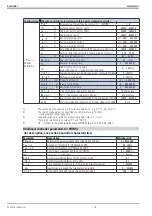
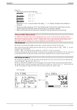
After a successful self-tuning attempt, the controller goes to the automatic mode and controls the setpoint using the
new parameters. Parameter
Ores
indicates the result of self-tuning completion (
r
see page 189) .
a
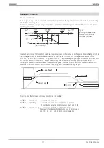
When self-tuning is finished with an error (
Ada_Err
), the stable correcting variable is output, until
self-tuning is finished by the operator via the system menu, front panel key H, or via the interface.
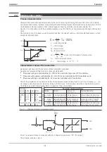
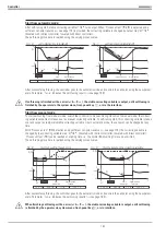
Self-tuning procedure with heating and cooling processes:
(3-point / split-range controller and mixed controllers)
With
PIDMA,
different control gains for heating and cooling cannot be specified. For this reason, the 2-step
self-tuning attempt is omitted.
Controller
9499 040 50611
Controller characteristics and self-tuning with PIDMA
188
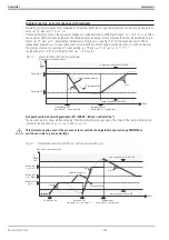
Fig.: 11
Selbstoptimierung [grad(x)=0]
Summary of Contents for KS 98
Page 8: ...Description 9499 040 50611 Construction 8...
Page 10: ...Important technical data 9499 040 50611 Further external in and outputs 10...
Page 12: ...Versions 9499 040 50611 I O modules for units with modular option c basic card 12...
Page 14: ...Front view 9499 040 50611 14...
Page 16: ...Mounting 9499 040 50611 16...
Page 26: ...Maintenance 9499 040 50611 Further information 26...
Page 36: ...Scaling and calculating functions 9499 040 50611 LG10 10s logarithm 36...
Page 74: ...Signal converters 9499 040 50611 MEAN mean value formation 74...
Page 128: ...KS98 I O extensions with CANopen 9499 040 50611 RM_DMS strain gauge module 128...
Page 132: ...CSEND Send mod blockno s 21 23 25 27 No 57 132...
Page 140: ...Description of KS98 CAN bus extension 9499 040 50611 140...
Page 202: ...Controller 9499 040 50611 Process value calculation 202...


