Magellan Developer’s Kit Electrical Specifications
48
Magellan Motion Processer Developer’s Kit Manual
3
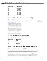
3.2.8
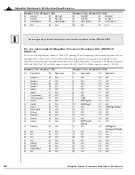
SPI Atlas Bus Connector (J14)
This is a female DB-9 connector.
This connector is designed to be compatible with the Atlas DK bus system of cables and cards. See
for more information on Atlas DKs
3.2.9
CANbus Connector (JS1)
This is a 4-pin mini-DIN connector.
3.3
Outputs to Motor Amplifiers
When connecting any axis to an Atlas amplifier the SPI ATLAS bus connector (J14) is used.
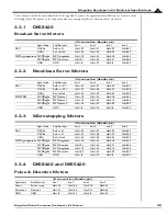
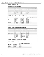
For axes that are not connected to Atlas amplifiers, there are four types of output to the motor amplifiers:
Pin number
Signal name
1 No
connection
2 Serial
Transmit
3 Serial
Receive
4 No
connection
5 Gnd
6 No
connection
7 No
connection
8 No
connection
9 No
connection
Pin number
Signal name
1
SPIEnable3
2
SPIEnable2
3
GND
4
GND
5
SPIRcv
6
SPIEnable1
7
SPIEnable4
8
SPIClock
9
SPIXmt
Pin number
Signal name
1
CANH
2
CANL
3
GND
4
No connection
DAC
Analog signals from the on-board D/A converters
PWM 50/50
Pulse-width modulated square-wave signals with a 50% duty cycle
PWM sign-magnitude
Pulse-width modulated signals with definable duty cycle and direction
Pulse & direction
Step-motor output digital pulse and direction signals


