Magellan Developer’s Kit Electrical Specifications
Magellan Motion Processer Developer’s Kit Manual
51
3
3.4
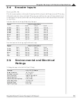
Encoder Inputs
Resistor packs RS1 - RS3
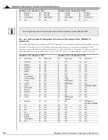
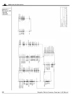
These three resistor packs are at the left end of the developer's kit board, next to the 100-pin connector J4. When using
differential encoders, leave these packs in place. When using open-ended encoders, remove all three packs and connect
encoder signals to the positive encoder input only. The negative input can be left unconnected. Encoder connections
are shown below.
Encoder connections when using differential encoder input
Encoder connections when using single-ended encoder input
3.5
Environmental and Electrical
Ratings
All ratings and ranges are for both the IO and CP chips.
Signal
J4 pin connections
Axis 1
Axis 2
Axis 3
Axis 4
Hdr1-1
Hdr1-26
Hdr1-51
Hdr1-76
QuadAn-
Hdr1-2
Hdr1-27
Hdr1-52
Hdr1-77
Hdr1-3
Hdr1-28
Hdr1-53
Hdr1-78
QuadBn-
Hdr1-4
Hdr1-29
Hdr1-54
Hdr1-79
Hdr1-5
Hdr1-30
Hdr1-55
Hdr1-80
Indexn-
Hdr1-6
Hdr1-31
Hdr1-56
Hdr1-81
Vcc
Hdr1-7
Hdr1-32
Hdr1-57
Hdr1-82
GND
Hdr1-8
Hdr1-33
Hdr1-58
Hdr1-83
Signal
J4 pin connections
Axis 1
Axis 2
Axis 3
Axis 4
QuadAn
Hdr1-1
Hdr1-26
Hdr1-51
Hdr1-76
QuadBn
Hdr1-3
Hdr1-28
Hdr1-53
Hdr1-78
Indexn
Hdr1-5
Hdr1-30
Hdr1-55
Hdr1-80
Vcc
Hdr1-7
Hdr1-32
Hdr1-57
Hdr1-82
GND
Hdr1-8
Hdr1-33
Hdr1-58
Hdr1-83
Dimensions
4.25" x 9.25", PCI Adapter
Storage Temperature
-40 °C to 125 °C
Operating Temperature
0 °C to 70 °C*
Power Consumption
1A @ 5V; 83mA @ 12V
Supply Voltage Limits
-0.3V to +7.0V
Supply Voltage Operating Range
4.75V to 5.25V
Analog Output Range
-10.0V to 10.0V
Analog Input Range
0.0V to 3.3V
Digital Output Range
0.0V to 3.3V


