Atlas Developer’s Kit
60
Magellan Motion Processer Developer’s Kit Manual
A
A.3.4.2
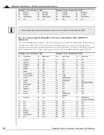
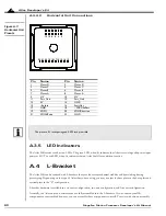
Horizontal Unit Connections
Figure A-7:
Horizontal Unit
Pinouts
A.3.5
LED Indicators
The Atlas DK carrier card has two LEDs. The green LED, when lit, indicates that Atlas is receiving valid power input
power at HV. The red LED, when lit, indicates that an Atlas FaultOut condition is active.
A.4
L-Bracket
The Atlas DK can be ordered with L-brackets that provide extra mechanical stability and heat sinking during
prototyping. Depending on the type of Atlas that you are using, you may use just the base plate or the base plate and
vertical plate in the “L” configuration.
L-bracket hardware is available in a one axis configuration, two axis configuration, and four axis configuration.
Normally, the Atlas units and carrier cards are fully assembled into the L-brackets. If you ordered your DK
components not assembled however, you can assemble these components yourself. To assist with this, an assembly
Pin
Name
Pin
Name
1
Motor D
2
Motor D
3
Motor C
4
Motor C
5
Motor B
6
Motor B
7
Motor A
8
Motor A
9
HV
10
HV
11
Pwr_Gnd
12
Pwr_Gnd
13
5V
14
GND
15
~Enable
16
FaultOut
17
GND
18
~SPICS/AtRest
19
SPISO
20
SPISI/Direction
21
SPIClk/Pulse
22
GND
The pins are 0.1 inch spacing and 0.025 inch pin width.
11 9 7 5 3 1
12 10 8 6 4 2
22 21 20 19 18 17 16 15 14 13

