Connecting the Eagle™
••••
WHEN CONNECTING THE SIGNAL MEASURING LEADS, DO
NOT TOUCH ANY OF THE CONNECTION POINTS. LETHAL
VOLTAGES MAY BE PRESENT WHICH CAN CAUSE SERIOUS
INJURY OR DEATH.
Below is the recommended process for connecting an Eagle
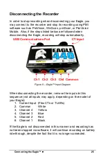
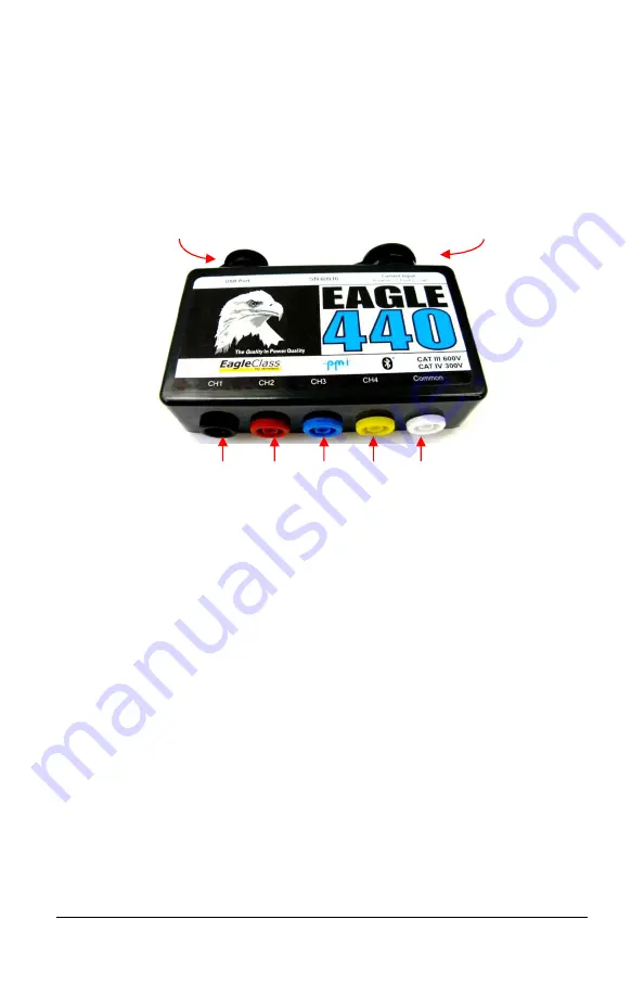
Figure 7 – Eagle™ Input Diagram
When connecting the recorder, connect the inputs in this
sequence (not all inputs may apply, depending on the model of
your Eagle):
1. CTs (Position CTs first, then connect to unit)
2. Common
White
3. Channel 4
Yellow
4. Channel 3
Blue
5. Channel 2
Red
6. Channel 1
Black
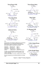
On the following page are diagrams showing several basic circuits
and possible ways to connect them using your Eagle recorder.
USB Communications Port
CT Input
Ch1
Ch2
Ch3 Ch4 Common
23
WHEN CONNECTING THE SIGNAL MEASURING LEADS, DO
NOT TOUCH ANY OF THE CONNECTION POINTS. LETHAL
VOLTAGES MAY BE PRESENT WHICH CAN CAUSE SERIOUS
recommended process for connecting an Eagle:
the inputs in this
sequence (not all inputs may apply, depending on the model of
are diagrams showing several basic circuits
d possible ways to connect them using your Eagle recorder.
CT Input


