COMPRESSOR
HOT GAS BYPASS VALVE
Refrigerant compressors normally do not need any
maintenance. The compressor will unload or adjust for
different load conditions with the refrigeration controls.
Any time power is applied to the compressor, and the
suction pressure is higher than the specified readings,
the compressor is either not pumping or failed
electrically, or tripped “off” at the overload protection. If
the compressor does not automatically reset within a few
minutes, it requires servicing. Service must be
performed by a qualified refrigeration technician.
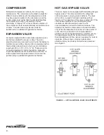
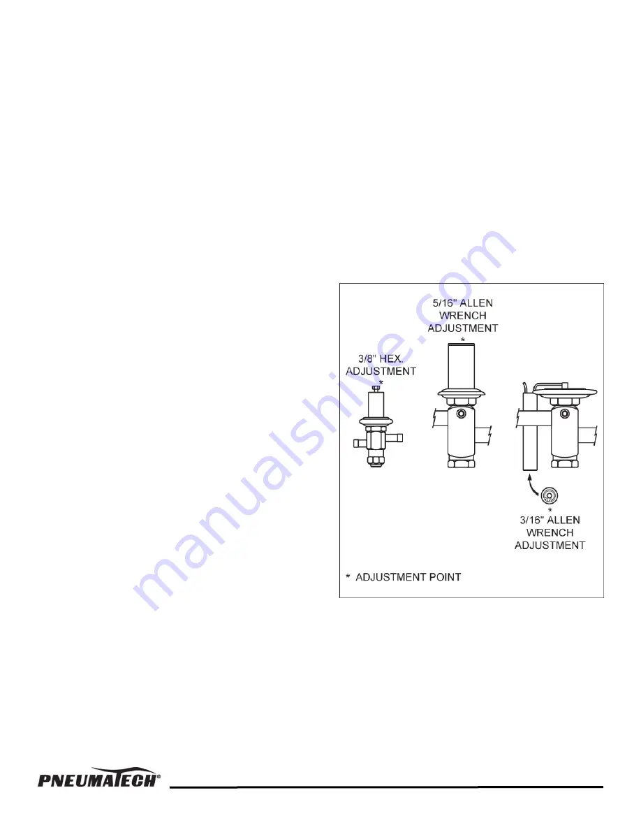
These air dryers come equipped with modulating hot gas
bypass valves. This valve maintains the refrigerant
suction pressure in varying load conditions. The dryer
will run from no load to full load conditions without
freeze-up. The operation of this valve is automatic. If the
valve needs adjustment, turn the adjusting stem
clockwise to raise the suction pressure, and
counterclockwise to lower the suction pressure. This
adjustment should be made under a no-load condition
only. When the adjustment is made, turn one quarter of
a turn at a time, and wait 3 to 5 minutes between
adjustments. Once the adjustment is complete, secure
the adjusting stem with the locknut that is provided.
Careful adjustment of this valve is necessary for normal
operation of the air dryer. Hot gas bypass valve
adjustment may be made by maintenance personnel.
See Figure 5.
EXPANSION VALVE
Air dryers equipped with an automatic expansion valve
are factory adjusted for proper cooling. The valve
adjusting stem is secured with a lock nut at the factory to
maintain proper setting. Larger units are equipped with a
thermostatic expansion valve, factory set to maintain a
superheat of 8 to 10°F (-13 to -12°C). These valves do
not need adjustment in normal operation. Generally,
superheat adjustments are needed only at the time of
valve replacement. Expansion valve service must be
performed by a qualified refrigeration technician.
FIGURE 5 — HOT GAS BYPASS VALVE ADJUSTMENTS
13
Summary of Contents for AD Series
Page 15: ...14 FIGURE 6 FLOW DIAGRAM AD 750 to 1000 ...
Page 16: ...15 FIGURE 7 FLOW DIAGRAM AD 1200 to 2000 ...
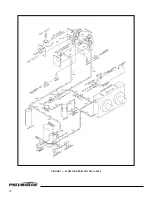
Page 17: ...FIGURE 8 FLOW DIAGRAM AD 2500 to 4000 16 ...
Page 22: ...21 ...
Page 23: ...22 ...


