background image

Pub. No. OM-A-10E — April 2004

11

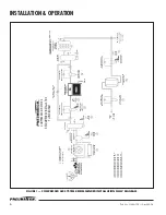
FIGURE 2 — SDG-1: SEQUENCE OF OPERATION DIAGRAM

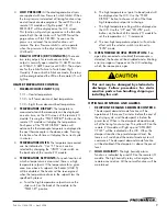
Shutdown Procedure

Externally Heated dryers are typically installed in 24 Hr. 
operations. The dryers operate on a standard time cycle 
of 8 hours, 4 hours drying and 4 hours regenerating. This 
cycle should not be interrupted (except for servicing). If the 
dryer needs to be shut down for a certain shift or 
weekend; the dryer should be turned off at the end of the 
4 hour regenerating cycle, and with both towers at line 
pressure. If servicing is required advance the time 
sequence so the purge valves close, and pressurize both 
towers. At this time, the dryer can be turned off.

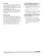
1.

If the compressed air system has been 
piped with a bypass around the dryer, then 
the following should be completed

:

a. Open the bypass valve to allow process flow to 

continue downstream, then close the dryer outlet 
isolation valve.

b. Turn the dryer ON/OFF switch to the OFF 

position.

c. Close the dryer inlet isolation valve on the dryer 

bypass piping. At this time the dryer is isolated 
and can be depressurized for servicing.

2.

If the compressed air system has not been 
piped with a bypass, then the following 
should be completed:

a. Turn the power switch to the OFF position.

b. The tower switching valves are normally open 

valves; therefore, with the power off the inlet 
valves to the towers will be open, and the purge 
valves will close. This will give you extended 
drying time until desiccant chambers are 
saturated.

1

LEFT TOWER
SWITCHING

ON 
OFF

ZERO

ZERO

240 MINUTES

240 MINUTES

480 MINUTES

480 MINUTES

ZERO

R TOWER

HEATING

R TOWER
COOLING

240 MINUTES

150

390

480 MINUTES

2

RIGHT TOWER
SWITCHING

ON 
OFF

3

LEFT TOWER
REGENERATING

ON 
OFF

4

RIGHT TOWER
REGENERATING

ON 
OFF

5

DEMAND
CYCLE

ON 
OFF

N/A

HEATER

TIMING STAGE:

ON 
OFF

6

LEFT TOWER
DEPRESSURIZING (OPT.)

ON 
OFF

7

RIGHT TOWER
DEPRESSURIZING (OPT.)

ON 
OFF

L TOWER

HEATING

L TOWER

COOLING

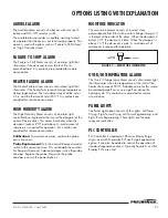
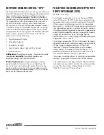
Summary of Contents for EE Series

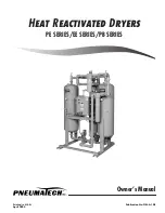
Page 1: ...Printed in U S A Publication No OM A 10E April 2004 Owner s Manual HEAT REACTIVATED DRYERS PE SERIES EE SERIES PB SERIES ...

Page 2: ... Doing this will extend the warranty to 24 months from date of shipment from Company s factory See back page for actual Warranty details DATE OF PURCHASE MODEL SERIAL NO Record above information from nameplate Retain this information for future reference Replacement Price 25 00 ...

Page 3: ...on Operation 7 General 7 Start Up Procedure 7 Adjustments Settings 8 DMP Microprocessor Control with Cycle Sight 8 Sequence of Operation 10 Shutdown Procedure 11 PB Series Heat Reactivated Blower Purge Air Dryer Installation Operation 13 General 13 Start Up Procedure 13 Adjustments Settings 14 Sequence of Operation 14 Dry Air Sweep 15 Shutdown Procedure 15 Maintenance 17 PE EE Series Heat Reactiva...

Page 4: ...Programming 19 Open Sensor Condition 19 Setpoint Limit Indication 19 Over Range and Under Range Indication 19 Peak Valley Indication 19 Options Listing with Explanation 21 Audible Alarm 21 Failure to Shift Alarm 21 Heater Failure Alarm 21 High Humidity Alarm 21 Moisture Indicator 21 Over Hi Temperature Alarm 21 Panel Lights 21 PLC Controller 21 Dewpoint Demand Control DPD 22 Pulse Purge Regenerati...

Page 5: ...o install equipment SERVICE INQUIRIES Provide Model No Serial No Operating Pressure Inlet Temperature Nature of Problem See Dryer Specification Tag located on the control panel SAFETY INSTRUCTIONS When using air compressors and compressed air accessories basic safety rules and precautions must always be followed including the following 1 READ ALL INSTRUCTIONS FULLY 2 WIRING BREAKERS Wiring breaker...

Page 6: ... be taken Refer to OSHA 29 CFR 1910 134 DISCLAIMER OF WARRANTY If this unit is used to produce breathing air the special equipment and precautions expressed in OSHA 29 CFR 1910 134 for specifications of the necessary equipment and special precautions to make Breathing Air MUST BE used or any warranties are VOID and manufacturer disclaims any liability whatsoever for loss personal injury or damage ...

Page 7: ...and larger use two sizes of desiccant For all heat reactivated models fill the tower with the 1 4 diameter Activated Alumina first followed by 1 8 Activated Alumina The large desiccant 1 4 size is used to disperse the inlet air flow 7 Close the fill ports and put the dryer in service Refer to the Start Up Procedure listed in this manual MOLECULAR SIEVE OPTION LOW DEWPOINT Dryers with optional Mole...

Page 8: ...GAUGE REMOVES 66 MOISTURE AIR COOLED AFTERCOOLER 2 P RECEIVER T C PREFILTER REGENERATIVE AIR DRYER PARTICULATE AFTERFILTER 4 5 TO PLANT USE 37 F RECEIVER REFRIGERATED COALESCING AFTERFILTER DRAIN R OPTIONAL 3 VALVE SYSTEM BYPASS P 6 P CONTROL OPTIONAL AUTO DRAIN 1 SEE PNEUMATECH BULLETIN PWC 1 2 SEE PNEUMATECH BULLETIN A 3 3 SEE PNEUMATECH BULLETIN A 16 4 SEE PNEUMATECH BULLETIN A 8 5 SEE PNEUMATE...

Page 9: ...esistance The element phase to ground should exceed the resistance value by 20 megohms If this value is not indicated energize the heater at low voltage to drive the moisture from the element insulation Remove the cover to vent the moisture from the heater terminal enclosure 11 STEAM CONNECTIONS For units with optional steam heat exchanger the steam connections are supplied as flanges for both inl...

Page 10: ...ation is based on an 8 hour NEMA Cycle with one half of the total time being for adsorption of moisture from the process gas and one half for desiccant regeneration Specifics of the timing sequence are detailed in Figure 2 the Sequence of Operation Diagram SDG 1 on Page 11 If power is interrupted the DMP controller electronically stores the point in the timing cycle at which power was removed When...

Page 11: ...at which a temperature is measured there is a high temperature setpoint If the temperature for a given area rises above its setpoint the heater LOAD 5 will be disabled The heater will be re energized when the temperature drops to the setpoint less the specified hysteresis a To set the high temperature setpoints move the slide switch on the back of the module to the TEMP SET position b The high tem...

Page 12: ...only Any liquids or slugs of water tend to decrease the efficiency of the desiccant and retard the regeneration process to provide the designed dewpoint With the power switch in the ON position at time equal to 0 0 hrs the left tower air inlet valve is open to allow the air to pass through the left tower The right tower inlet valve is closed The saturated compressed air gas passes through the desi...

Page 13: ...lose the dryer outlet isolation valve b Turn the dryer ON OFF switch to the OFF position c Close the dryer inlet isolation valve on the dryer bypass piping At this time the dryer is isolated and can be depressurized for servicing 2 If the compressed air system has not been piped with a bypass then the following should be completed a Turn the power switch to the OFF position b The tower switching v...

Page 14: ...VALVE 12 TEMPERATURE GAUGE 14 ELECTRIC HEATER 15 HEATER CHAMBER 16 HEATER CONTROL THERMOSTAT 17 OVER TEMPERATURE THERMOSTAT 18 PURGE ISOLATION VALVE OPTIONAL 19 PURGE ORIFICE ASSEMBLY 20 PURGE ADJUSTMENT PRESSURE GAUGE 22 PILOT AIR SHUT OFF VALVE 23 PILOT AIR FILTER 24 MOISTURE INDICATOR OPTIONAL 25 4 WAY LEFT TOWER SWITCHING SOLENOID 27 4 WAY LEFT TOWER PURGE SOLENOID 29 4 WAY PURGE ISOLATION SOL...

Page 15: ...lement phase to ground should exceed the resistance value by 20 megohms If this value is not indicated energize the heater at low voltage to drive the moisture from the element insulation Remove the cover to vent the moisture from the heater terminal enclosure 11 STEAM CONNECTIONS For units with optional steam heat exchanger the steam connections are supplied as flanges for both inlet and condensa...

Page 16: ...wer switch in the ON position at time equal to 0 0 hrs the left tower air inlet valve is open to allow the air to pass through the left tower The right tower inlet valve is closed The saturated compressed air gas passes through the desiccant in the left tower where the desiccant adsorbs the moisture and the dry air at a pressure dewpoint of 40 F or less exits through the left outlet check valve an...

Page 17: ...ould be turned off at the end of the 4 hour regenerating cycle and with both towers at line pressure If servicing is required advance the time sequence so the purge valves close and both towers pressurize At this time the dryer can be turned off 1 If the compressed air system has been piped with a bypass around the dryer then the following should be completed a Open the bypass valve to allow proce...

Page 18: ...L 2 AIR INLET VALVE 4 PURGE FLOW CHECK VALVE 8 9 DESICCANT SCREEN 11 PRESSURE GAUGE 12 TEMPERATURE GAUGE 13 DESICCANT THERMOSTAT 14 ELECTRIC HEATER 16 HEATER CONTROL THERMOSTAT 17 18 COOLING FLOW REPRESSURIZING VALVE 19 PURGE ORIFICE ASSEMBLY 20 PURGE ADJUSTMENT PRESSURE GAUGE 22 PILOT AIR SHUT OFF VALVE 26 27 FLEX CONNECTOR 29 THROTTLING VALVE 30 BACK FLOW PREVENTION CHECK VALVE 31 4 WAY LEFT TOW...

Page 19: ...essary 3 Blow down relief valves 4 Check outlet dewpoint conditions Twelve Months 1 Close the inlet and outlet valves on the dryer or bypass the dryer and completely depressurize the dryer system Open the desiccant fill port and check visually If desiccant is contaminated with oil or broken replace the desiccant 2 Check for leaking check valves per Table 1 symptoms C D in Troubleshooting Guide Rep...

Page 20: ...e filter Replace if necessary Three Months 1 Every three 3 months check for any leaks in the inlet and or check valves indicated by air coming through the exhaust mufflers when the blower is off 2 Check the prefilter and afterfilter elements for excessive clogging or possible damage Replace as necessary 3 Blow down relief valves 4 Check outlet dewpoint conditions Twelve Months 1 Close the inlet an...

Page 21: ...nge of the hygrometer OVER RANGE AND UNDER RANGE INDICATION For Ceramic Sensor Probes 1 When the hygrometer detects the maximum value of the Measurement range 68 F flashes on the display 2 When the hygrometer detects the minimum value of the Measurement range 148 F flashes on the display For Aluminum Oxide Sensor Probes Dryers built prior to Year 2000 1 When the hygrometer detects the maximum valu...

Page 22: ...20 Pub No OM A 10E April 2004 FIGURE 6 DEWPOINT DISPLAY CONTROL WIRING ...

Page 23: ...robe every two years Probe Replacement Turn the normal demand selector switch to the normal position This will disable the contacts for Dewpoint Demand Isolate and depressurize the probe chamber Replace the probe Pressurize the probe chamber and turn the power back on MOISTURE INDICATOR The moisture indicator consists of a small clear polycarbonate filter filled with a color change silica gel It i...

Page 24: ...ble A small amount of sample air approximately 2 10 SCFH should expel out the chamber needle valve PULSE PURGE REGENERATION PPR WITH DEWPOINT DEMAND DPD PE EE Series only Pulse Purge Regeneration systems use the same NEMA cycle of 8 hours as PE EE Series dryers except during the regeneration cycle instead of continuously flowing 7 of the purge air and blowing it out into the atmosphere the purge a...

Page 25: ... pressure on regenerating tower 4 Heater burnout 5 Contactor faulty 6 No power 7 Insufficient heating period 1 Reset thermostat or replace if necessary 2 See A1 3 See C1 4 Check heater replace if necessary 5 Replace heater contactor 6 Check for continuity 7 Contact factory C High back pressure on regenerat ing tower NOTE The tower should be at 0 PSIG during regeneration cycle Any back pressure wil...

Page 26: ...r if necessary 2 Replace timer 3 Clean or replace pilot filter element 4 Repair or replace pilot air cylinder G High pressure drop in dryer 1 Desiccant retainer screens plugged 2 Excess flow 3 High purge flow 4 Purge valve stays open 5 Repressurizing valve stays open 1 Replace desiccant retainer screens 2 Check inlet flow conditions 3 Check and reset purge pressure 4 Check repressurizing solenoid ...

Page 27: ... regenerating tower does not pressurize fully desiccant attrition takes place at the time of tower switch over 1 See K L 2 Excess flow due to greater demand in process or addition of extra compressors 2 Check outlet flow N Dewpoint Spike NOTE Blower purge dryers may spike during normal operation due to blower cooling 1 Excessive residual heat in newly regenerated tower 1 Lower heater thermostat se...

Page 28: ...tive dryers and valves on Intermediate Controls for defects in material or workmanship covering Components only provided a Customer notified the Company of any claim of defect in material or workmanship within sixty 60 months from date of shipment from the Company s factory b Customer holds the Product or Component for inspection by the Company s representative c Customer returns the Component s o...

Reviews: