
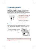


14
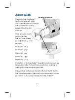
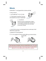
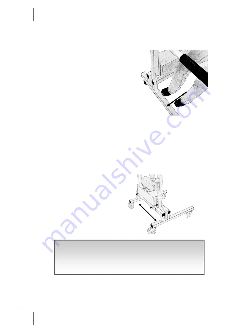
Narrow to Wide
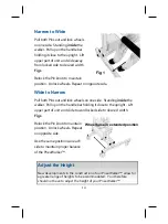
Pull both Pins out and lock wheels
on one side. Standing
inside
the
walker. Pull up on the handle bar
holding it close to the upright. Lift
upper part of unit and slide away
from locked side to desired width.
Fig 1
Relock the Pin knob to maintain
position. Unlock wheels. Repeat on opposite side.
Wide to Narrow
Pull both Pins out and lock wheels on one side. Standing
inside
the
walker. Pull up on the handle bar holding it close to the upright. Lift
upper part of unit and slide toward locked side to desired width.
Fig 1
Relock the Pin knob to maintain
position. Unlock wheels. Repeat
on opposite side.
Use the same positions on each
side to maintain proper balance
of the PneuWalker™.
Wheel base in extended position
Fig 1
Adjust the Height
New developments in the construction of our PneuWalker™ allow for
a greater range of heights to be accommodated. You therefore
should not have to adjust the height of your PneuWalker™.


