background image

Benutzerhandbuch

D

eu

tsc

he

31

Technische Spezifikationen


»

Motorbetriebstemperatur: -26°C ~ + 80°C


»

Stromversorgung der Steuereinheit: 230 V


»

Leistung: 350W


»

Übertragungsmodus Ausgang: M = 4


»

Drehmoment: 30,0 Nm


»

Öffnungs-/Schließgeschwindigkeit: 12m/min


»

Umdrehungen: 1400 U/min


»

Zugkraft: 1100 N (Newton)


»

Maximale Traglast: 800 kg


»

Maximale Kommunikationsentfernung mit Fernbedienung: 50 m 

Haupteigenschaften


»

Anschlussmöglichkeit für Lichtschranke (im Lieferumfang enthalten), 

Zugangstastatur, Zugangstaster und weiteres Zubehör für die 

Zugangskontrolle


»

Möglichkeit zum Anschluss der Sicherheitslampe (im Lieferumfang 

enthalten)


»

Automatische Schließung


»

Einstellbare Empfindlichkeit


»

Hindernisschutz: Das Tor stoppt und öffnet sich wieder, wenn es beim 

Schließen auf ein Hindernis trifft; das Tor stoppt, wenn es beim Öffnen 

auf ein Hindernis trifft. Die Kraft, mit der das Tor stoppt, wenn es auf 

ein Hindernis trifft, ist sowohl beim Schließen als auch beim Öffnen 

einstellbar.


»

Die Möglichkeit, 2 Motoren im Spiegel (gegenüber) zu montieren, um 

die Länge des Tor-/Öffnungsbereichs zu verdoppeln. So öffnet sich links 

und rechts ein Tor

Summary of Contents for AP800C

Page 1: ...z l si k szlet Kit automazione cancello scorrevole Automatiseringskit schuifpoort Zestaw automatyki do bram przesuwnych Kit automatizare porti autoportante EN User manual 3 BG 15 DE Benutzerhandbuch 2...

Page 2: ......

Page 3: ...ing on the board will fail Safety information Do not replace components and accessories other than those included or recommended by the manufacturer Before powering the system make sure that all conne...

Page 4: ...s your duty to ensure the safe operation of the gates Note We do not take responsibility for any accidents or defects caused by improper installation of the gate automation system Package contents Con...

Page 5: ...ed access keyboard access button and other access control accessories Possibility to connect the safety lamp included Automatic closing Adjustable sensitivity Obstacle protection the gate stops and re...

Page 6: ...allation location carefully Temporarily place the engine mounting base at a distance of 35 mm from the gate Diagram 1 Put the engine on the stand Test with a piece of rack positioned on the gear wheel...

Page 7: ...make sure the rack slides well on the gear Assemble the following pieces of rack making sure they are perfectly in line with each other Manually move the gate back and forth after each piece of rack i...

Page 8: ...the race Mainboard 13 1 Pairing the remote control Press the LEARN button on the board 13 1 The D5 LED will flash for 10 seconds During this time press any key on the remote control If the code has be...

Page 9: ...control with 2 automation systems 13 2 Obstacle detection We can set two sensitivity levels High and Low A High sensitivity if the gate is opening or closing and encounters a small obstacle then the e...

Page 10: ...e engine will stop automatically If you press button 2 or 4 on the remote control to open the gate it will close after the programmed time 5 10 or 30 seconds or will remain open if automatic closing h...

Page 11: ...e will stop D6 Led on gate opening D7 Led on door closed D8 LED on the Mainboard is powered 13 6 Terminal stop detection interface Ithas2modes oneopensthegateandoneclosesthegateinnormaloperation 13 7...

Page 12: ...of the gate seen from the inside Terminal 4 connect the red wire to the motor Terminal 5 connect the blue wire to the motor Terminal 3 connect the yellow wire to the motor Note For mounting the motor...

Page 13: ...ared sensor connection Remove the wire between terminal 14 and 15 Connect terminal 15 to the COM terminal and terminal 14 to the OUT terminal of the sensor Terminals 12 and 13 power the sensor Thus co...

Page 14: ...example when connecting an access button Connect the access button to terminals 10 and 11 Terminals 12 and 13 are for powering the access button Maintenance instructions The rack and gear must always...

Page 15: ...15...

Page 16: ...16 2 x 2 1 6 1 1 x...

Page 17: ...17 26 C 80 C 230V 350W M 4 30 0 N m 12 1400 1100N 800 50 m 2...

Page 18: ...18 10A 35 1 4 2 4...

Page 19: ...19 2 3 mm...

Page 20: ...20 10A 1...

Page 21: ...21 13 1 Paring the remote control LEARN 13 1 D5 10 D5 D5 10 LEARN 6 D5 20 D5 5 1 2 1 2 3 4...

Page 22: ...22 3 4 3 4 2 13 2 A B 13 3 1 OFF NC ON NO 2 OFF NO ON NC 3 4 OFF 3 4 10 4 OFF 4 ON 30 5 ON 4 ON 60 5 6 OFF 6 6 5 7 OFF 6 ON...

Page 23: ...23 10 8 ON 6 ON 30 2 4 2 4 2 4 5 10 30 2 4 7 ON 13 4...

Page 24: ...24 13 5 LED D1 LED D2 LED D3 LED D4 D6 D7 D8 LED 13 6 2 13 7 J1 J1 13 6 Jumper J1 1 NO1 NO2 2 NO2 NO3...

Page 25: ...25 6 7 230V 3 4 5 4 5 3 4 5 3...

Page 26: ...26 14 15 15 COM 14 OUT 12 13 12 13...

Page 27: ...27 NO NO 11 10 11 12 13 3...

Page 28: ...28...

Page 29: ...rdrahtung auf der Platine ausf llt Sicherheitsinformation Ersetzen Sie nur die vom Hersteller mitgelieferten oder empfohlenen Komponenten und Zubeh rteile Stellen Sie vor dem Einschalten des Systems s...

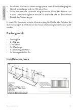
Page 30: ...ernisse wie Kinder Tiere oder Gegenst nde nicht Es ist Ihre Pflicht f r den sicheren Betrieb der Tore zu sorgen Hinweis Wir bernehmen keine Verantwortung f r Unf lle oder Defekte die durch unsachgem e...

Page 31: ...ten Zugangstastatur Zugangstaster und weiteres Zubeh r f r die Zugangskontrolle M glichkeit zum Anschluss der Sicherheitslampe im Lieferumfang enthalten Automatische Schlie ung Einstellbare Empfindlic...

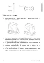
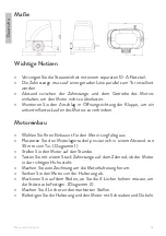
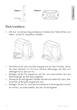
Page 32: ...rn Motoreinbau W hlen Sie Ihren Einbauort f r den Motor sorgf ltig aus Platzieren Sie den Motorlagersockel provisorisch in einem Abstand von 35 mm vom Tor Diagramm 1 Stellen Sie den Motor auf den St n...

Page 33: ...bstand von 2 3 mm zwischen Zahnstange und Rad und befestigen Sie es dann am Tor Bewegen Sie das Tor manuell hin und her um sicherzustellen dass die Zahnstange gut auf dem Zahnrad gleitet Montieren Sie...

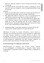
Page 34: ...nde erreicht wenn das Tor ge ffnet oder geschlossen wird Stromversorgung und Installationspr fung berpr fen Sie die Kabel und Anschl sse erneut Schlie en Sie das Tor manuell Schlie en Sie das System a...

Page 35: ...Sie die LEARN Taste 6 Sekunden lang gedr ckt die D5 LED blinkt lassen Sie die Taste los Jetzt sind alle gespeicherten Codes gel scht Das System kann maximal 20 Fernbedienungen lernen Wenn Sie versuche...

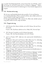
Page 36: ...on ON Die Fotozelle befindet sich im NC Modus 3 und 4 in Position OFF deaktiviert die automatische Schlie funktion Default 3 auf Position ON und 4 auf Position OFF Wenn das Tor vollst ndig ge ffnet is...

Page 37: ...Zugangstastatur dr cken funktionieren diesenicht bisdasTorvollst ndigge ffnetist WenndasTorgeschlossenistund Sie die Tasten auf der Fernbedienung oder einem anderen angeschlossenen Zugangsterminal dr...

Page 38: ...teilt der Klemme 13 6 die ffnungs und Schlie richtung des Tors mit Jumper J1 Varianten 1 NO1 NO2 Normale ffnung Motor links vom Tor innen 2 NO2 NO3 ffnen in die entgegengesetzte Richtung Motor rechts...

Page 39: ...n Motor an Klemme 5 Schlie en Sie das blaue Kabel an den Motor an Klemme 3 Schlie en Sie das gelbe Kabel an den Motor an Hinweis Wenn Sie den Motor auf der rechten Seite des Tors Innenansicht montiere...

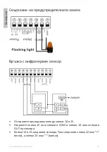
Page 40: ...Infrarotsensor Entfernen Sie das Kabel zwischen Klemme 14 und 15 Verbinden Sie Klemme 15 mit der COM Klemme und Klemme 14 mit der OUT Klemme des Sensors Die Klemmen 12 und 13 versorgen den Sensor Ver...

Page 41: ...asters Schlie enSiedenZugangstasterandieKlemmen10und11an DieAnschl sse 12 und 13 dienen der Stromversorgung des Zugangstasters Wartungshinweise Die Zahnstange und das Getriebe m ssen immer sauber geha...

Page 42: ...que la placa base se calentar y el cableado de la placa fallar Informaci n de seguridad No reemplace componentes y accesorios que no sean los incluidos o recomendados por el fabricante Antes de alimen...

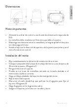
Page 43: ...culos como ni os animales u objetos Es su deber garantizar el funcionamiento seguro de las puertas Nota No nos hacemos responsables de ning n accidente o defecto causado por una instalaci n incorrecta...

Page 44: ...c lula incluida teclado de acceso bot n de acceso y otros accesorios de control de acceso Posibilidad de conectar la l mpara de seguridad incluida Cierre autom tico Sensibilidad ajustable Protecci n c...

Page 45: ...in control Instalaci n del motor Elija cuidadosamente la ubicaci n de instalaci n de su motor Coloque temporalmente la base de montaje del motor a una distancia de 35 mm de la puerta Diagrama 1 Ponga...

Page 46: ...e la cremallera y la rueda luego f jela en la puerta Mueva manualmente la compuerta hacia adelante y hacia atr s para asegurarse de que la cremallera se deslice bien sobre el engranaje Ensamble las si...

Page 47: ...al final cuando se abre o se cierra la puerta Pruebas de instalaci n y suministro de energ a Vuelva a revisar los cables y conexiones Cerrar la puerta manualmente Conecte el sistema a una fuente de al...

Page 48: ...te del modo de aprendizaje Mantenga presionado el bot n LEARN durante 6 segundos el LED D5 parpadear suelte el bot n Ahora todos los c digos que se guardaron se han eliminado El sistema puede aprender...

Page 49: ...ci n 1 Posici nOFF elmotorest enmodoNC NormalClose predeterminado Posici n ON el motor est en NO modo Normal Abierto 2 Posici n OFF la fotoc lula est en modo NO predeterminado Posici n ON la fotoc lul...

Page 50: ...s o permanecer abierta si se ha desactivado el cierre autom tico o pulse de nuevo el bot n 2 o 4 para cerrar la puerta inmediatamente 7 Posici n OFF desactiva el modo condominio Posici n ON activa el...

Page 51: ...base est alimentada 13 6 Interfaz de detecci n de parada de terminal Tiene 2 modos uno abre la puerta y otro cierra la puerta en funcionamiento normal 13 7 Configuraci n de l mite de apertura cierre...

Page 52: ...4 conecte el cable rojo al motor Terminal 5 conecte el cable azul al motor Terminal 3 conecte el cable amarillo al motor Nota Para montar el motor en el lado derecho de la puerta vista interior cuand...

Page 53: ...exi n del sensor de infrarrojos Retire el cable entre los terminales 14 y 15 Conecte el terminal 15 al terminal COM y el terminal 14 al terminal OUT del sensor Los terminales 12 y 13 alimentan el sens...

Page 54: ...conectar un bot n de acceso Conecte el bot n de acceso a los terminales 10 y 11 Los terminales 12 y 13 son para alimentar el bot n de acceso Instrucciones de mantenimiento La cremallera y el equipo de...

Page 55: ...a et le c blage sur la carte tombera en panne Information sur la s curit Ne remplacez pas les composants et accessoires autres que ceux inclus ou recommand s par le fabricant Avant de mettre le syst m...

Page 56: ...ls que des enfants des animaux ou des objets Il est de votre devoir d assurer le fonctionnement s curitaire des portes Remarque Nous d clinons toute responsabilit en cas d accidents ou de d fauts caus...

Page 57: ...ule incluse le clavier d acc s le bouton d acc s et d autres accessoires de contr le d acc s Possibilit de connecter la lampe de s curit incluse Fermeture automatique Sensibilit r glable Protection co...

Page 58: ...ani re incontr lable Installation du moteur Choisissez soigneusement l emplacement d installation de votre moteur Placer provisoirement le support moteur une distance de 35 mm du portail Sch ma 1 Mett...

Page 59: ...2 3 mm entre la cr maill re et la roue puis le fixer sur le doigt D placez manuellement la porte d avant en arri re pour vous assurer que la cr maill re glisse bien sur l engrenage Assemblez les l men...

Page 60: ...e arrive en fin de course lorsque le portail est ouvert ou ferm Test d alimentation et d installation V rifiez nouveau les c bles et les connexions Fermez le portail manuellement Connectez le syst me...

Page 61: ...ge de la t l commande si vous appuyez sur le bouton 1 ou le bouton 2 de la t l commande alors le bouton 1 commandera le portail en mode depuis la voiture ouvert arr t ferm et le bouton 2 actionnera le...

Page 62: ...i ton lorsque le portail est compl tement ouvert il se referme automatiquement au bout de 5 secondes 7 sur la position OFF et 6 sur la position ON en mode pi ton lorsque le portail est compl tement ou...

Page 63: ...st compl tement ferm D2 LED allum e le portail n est pas compl tement ouvert Voyant teint le portail est compl tement ouvert D3 LED allum e si vous donnez par exemple la commande d ouverture partir de...

Page 64: ...ch ma d installation des composants lectriques Les bornes 6 et 7 sont pour la connexion 230V Il est conseill d installer le moteur droite du portail vu de l int rieur Borne 3 connectez le fil rouge au...

Page 65: ...ntage du moteur sur le c t droit du portail vue int rieure lorsque vous changez le fil noir et le fil vert v rifiez si le moteur se ferme et s arr te normalement Sinon changez la position du cavalier...

Page 66: ...maintenez le cavalier en position NO comme le montre l image ci dessus Ouverture de la connexion de l appareil Si vous ne souhaitez pas utiliser la t l commande pour contr ler les portails connectez l...

Page 67: ...s Lubrifie toutes les pi ces mobiles du syst me d automatisation une fois tous les 3 mois Si la centrale est aliment e par une batterie de secours v rifiez la batterie tous les mois et remplacez la si...

Page 68: ...Biztons gi inform ci k Ne cser lje ki a gy rt ltal mell kelt vagy aj nlottakon k v li alkatr szeket s tartoz kokat Miel tt bekapcsoln a rendszert gy z dj n meg arr l hogy minden csatlakoz s s k bel j...

Page 69: ...t vagy t rgyakat Az n k teless ge a kapuk biztons gos m k d s nek biztos t sa Megjegyz s Nem v llalunk felel ss get a kapuautomatiz l si rendszer nem megfelel telep t s b l ered balesetek rt vagy hib...

Page 70: ...g a fotocella tartoz k bel ptet billenty zet bel ptet gomb s egy b bel ptet tartoz kok csatlakoztat s ra Lehet s g a biztons gi l mpa csatlakoztat s ra tartoz k Automatikus z r s ll that rz kenys g Ak...

Page 71: ...ny thatatlan m k d s t Motor beszerel s Gondosan v lassza ki a motor be p t si hely t Ideiglenesen helyezze a motortart alapot 35 mm t vols gra a kaput l 1 diagram Helyezze a motort az llv nyra Ellen...

Page 72: ...s helyet a fogasl c s a ker k k z tt majd r gz tse a kapun K zzel mozgassa a kaput el re h tra hogy megbizonyosodjon arr l hogy a fogasl c j l cs szik a fogasker ken Szerelje sszeak vetkez llv nydarab...

Page 73: ...el ri a v g t amikor a kaput kinyitj k vagy z rj k T pell t s s telep t s tesztel se Ellen rizze jra a k beleket s a csatlakoz sokat K zzel z rja be a kaput Csatlakoztassa a rendszert egy 10A es t peg...

Page 74: ...agy 2 es gombj t akkor az 1 es gomb aut b l m dban vez rli a kaput nyit meg ll z r a 2 es gomb pedig gyalogos zemm dban m k dteti a kaput m dban A 3 as s 4 es gombnak nincs funkci ja A tanul si folyam...

Page 75: ...amikor a kapu teljesen nyitva van 30 m sodperc m lva automatikusan bez r dik Megjegyz sek A 2 es s 4 es gombok a t vir ny t p ros t s t l f gg en a kaput gyalogos m dban m k dtetik Ha a motor j r s me...

Page 76: ...e hogy ugyanazt a parancsot adta ki D4 Led vil g t az infrav r s rz kel k nem szleltek semmilyen akad lyt LED nem vil g t az infrav r s rz kel k akad lyt szleltek A motor le ll D6 Led vil g t kapunyit...

Page 77: ...csatlakoz sra szolg l Javasoljuk hogy a motort a kaput l jobbra szerelje bel lr l n zve 3 kapocs csatlakoztassa a piros vezet ket a motorhoz 4 kapocs csatlakoztassa a s rga vezet ket a motorhoz 5 kap...

Page 78: ...a motorhoz Megjegyz s Ha a motort a kapu jobb oldal ra szereli bel ln zet a fekete s a z ld vezet k cser jekor ellen rizze hogy a motor megfelel en z r e s le ll e Ha nem v ltoztassa meg a J1 jumper...

Page 79: ...t NEM ll sban ahogy a fenti k pen is l that K sz l kcsatlakoz s megnyit sa Ha nem k v nja a t vir ny t t haszn lni a kapuk vez rl s re csatlakoztassa a k ls kapu m k dtet t a 11 es termin lhoz p ld ul...

Page 80: ...omatiz l si rendszer minden mozg r sz t Ha a vez rl panel tartal k akkumul torral m k dik havonta ellen rizze az akkumul tort s sz ks g eset n cser lje ki Rendszeresen ellen rizze a k belek s csatlako...

Page 81: ...madre si surriscalda e il cablaggio sulla scheda si guasta Informazioni sulla sicurezza Non sostituire componenti e accessori diversi da quelli inclusi o consigliati dal produttore Prima di alimentare...

Page 82: ...ome bambini animali o oggetti vostro dovere garantire il funzionamento sicuro dei cancelli Nota Non ci assumiamo alcuna responsabilit per eventuali incidenti o difetti causati da un installazione impr...

Page 83: ...clusa la tastiera di accesso il pulsante di accesso e altri accessori per il controllo degli accessi Possibilit di collegare la lampada di sicurezza inclusa Chiusura automatica Sensibilit regolabile P...

Page 84: ...zione di installazione del motore Posizionare provvisoriamente la base porta motore ad una distanza di 35 mm dal cancello Diagramma 1 Metti il motore sul cavalletto Testare con un pezzo di cremagliera...

Page 85: ...remagliera scorra bene sull ingranaggio Assembla i seguenti pezzi di cremagliera assicurandoti che siano perfettamente allineati tra loro Spostare manualmente il cancello avanti e indietro dopo ogni p...

Page 86: ...della corsa Scheda principale 13 1 Abbinamento del telecomando Premere il pulsante APPRENDIMENTO sulla lavagna 13 1 Il LED D5 lampegger per 10 secondi Durante questo tempo premere un tasto qualsiasi...

Page 87: ...t pedonale modalit In questo modo possibile abbinare lo stesso telecomando a 2 sistemi di automazione 13 2 Rilevamento ostacoli Possiamo impostare due livelli di sensibilit Alta e Bassa A Alta sensibi...

Page 88: ...te Se si preme il pulsante 2 o 4 del telecomando per aprire il cancello si chiuder dopo il tempo programmato 5 10 o 30 secondi oppure rimarr aperto se stata disattivata la chiusura automatica oppure s...

Page 89: ...Il motore si fermer D6 Led acceso cancello in apertura D7 Led acceso porta chiusa D8 LED acceso la Mainboard alimentata 13 6 Interfaccia di rilevamento dell arresto del terminale Dispone di 2 modalit...

Page 90: ...il collegamento a 230V Si consiglia di installare il motore a destra del cancello visto dall interno Morsetto 3 collegare il filo rosso al motore Morsetto 4 collegare il filo giallo al motore Morsetto...

Page 91: ...del motore sul lato destro del cancello vista interna quando si cambia il filo nero e il filo verde verificare se il motore chiude e si arresta normalmente In caso contrario modificare la posizione d...

Page 92: ...l ponticello in posizione NO come mostrato nell immagine sopra Apertura della connessione del dispositivo Se non si desidera utilizzare il telecomando per comandare i cancelli collegare l attuatore ca...

Page 93: ...e ante Lubrifica tutte le parti mobili del sistema di automazione una volta ogni 3 mesi Se la centrale alimentata da una batteria tampone controllare la batteria mensilmente e sostituirla se necessari...

Page 94: ...ken NIET lassen terwijl de motor is gemonteerd omdat het moederbord dan warm wordt en de bedrading op het bord uitvalt Veiligheidsinformatie Vervang geen andere onderdelen en accessoires dan die zijn...

Page 95: ...iligheidssensoren detecteren mogelijk geen kleine obstakels zoals kinderen dieren of voorwerpen Het is uw plicht om de veilige werking van de poorten te verzekeren Opmerking wij nemen geen verantwoord...

Page 96: ...sknop en andere accessoires voor toegangscontrole aan te sluiten Mogelijkheid om de veiligheidslamp aan te sluiten meegeleverd Automatisch sluiten Instelbare gevoeligheid Obstakelbeveiliging het hek s...

Page 97: ...es de installatielocatie van uw motor zorgvuldig Plaats de motorophangingsbasis tijdelijk op een afstand van 35 mm van de poort Diagram 1 Zet de motor op de standaard Test met een stuk tandheugel op h...

Page 98: ...tandheugel goed op het tandwiel schuift Monteer de volgende stukken rek en zorg ervoor dat ze perfect op elkaar aansluiten Beweeg de poort handmatig heen en weer na elk stuk rek dat is ge nstalleerd...

Page 99: ...en wanneer het het einde van zijn run bereikt Moederbord 13 1 De afstandsbediening koppelen Druk op de LEARN knop op het bord 13 1 De D5 LED zal 10 seconden knipperen Druk gedurende deze tijd op een w...

Page 100: ...in voetgangers bedienen modus Zo koppel je dezelfde afstandsbediening aan 2 automatiseringssystemen 13 2 Obstakeldetectie We kunnen twee gevoeligheidsniveaus instellen Hoog en Laag A Hoge gevoelighei...

Page 101: ...rukt stopt de motor automatisch Alsuopknop2of4vandeafstandsbedieningdruktomhethekteopenen zal het na de geprogrammeerde tijd 5 10 of 30 seconden sluiten of open blijven indien automatisch sluiten gede...

Page 102: ...en een obstakel gedetecteerd De motor zal stoppen D6 Led aan poort openen D7 Led aan deur gesloten D8 LED aan het moederbord is ingeschakeld 13 6 Terminal stop detectie interface Het heeft 2 modi n op...

Page 103: ...aansluiting We raden aan om de motor rechts van de poort te installeren van binnenuit gezien Terminal 3 sluit de rode draad aan op de motor Terminal 4 sluit de gele draad aan op de motor Terminal 5 s...

Page 104: ...monteren van de motor aan de rechterkant van de poort binnenaanzicht controleer bij het verwisselen van de zwarte en de groene draad of de motor normaal sluit en stopt Zo niet verander dan de positie...

Page 105: ...umper in de NEE positie zoals te zien is in de afbeelding hierboven Apparaatverbinding openen Als u de afstandsbediening niet wilt gebruiken om de poorten te bedienen sluit dan de externe poortactuato...

Page 106: ...t alle bewegende delen van het automatiseringssysteem eens per 3 maanden Als de centrale van stroom wordt voorzien door een back up batterij controleer dan maandelijks de batterij en vervang deze indi...

Page 107: ...em poniewa p yta g wna nagrzewa si a okablowanie na p ycie ulegnie awarii Informacje dotycz ce bezpiecze stwa Nie wymieniaj element w i akcesori w innych ni do czone lub zalecane przez producenta Prze...

Page 108: ...akich jak dzieci zwierz ta lub przedmioty Twoim obowi zkiem jest zapewnienie bezpiecznego dzia ania bram Uwaga Nie ponosimy odpowiedzialno ci za wypadki i usterki powsta e w wyniku nieprawid owego mon...

Page 109: ...u przycisku dost pu i innych akcesori w kontroli dost pu Mo liwo pod czenia lampy bezpiecze stwa w zestawie Automatyczne zamykanie Regulowana czu o Ochrona przed przeszkodami brama zatrzymuje si i otw...

Page 110: ...jsce instalacji silnika Tymczasowo umie podstaw mocowania silnika w odleg o ci 35 mm od bramy Schemat 1 Umie silnik na stojaku Sprawd z kawa kiem z batki umieszczonej na kole z batym czy silnik jest n...

Page 111: ...by upewni si e z batka dobrze lizga si na przek adni Z nast puj ce elementy stela a upewniaj c si e s idealnie dopasowane do siebie R cznie przesuwaj bram w prz d i w ty po zainstalowaniu ka dego elem...

Page 112: ...rowanie pilota Naci nij przycisk LEARN na tablicy 13 1 Dioda D5 b dzie miga przez 10 sekund W tym czasie naci nij dowolny klawisz na pilocie Je li kod zosta nauczony dioda D5 mignie dwa razy Pilot jes...

Page 113: ...przeszk d Mo emy ustawi dwa poziomy czu o ci Wysoki i Niski A Wysoka czu o je li brama otwiera si lub zamyka i napotka ma przeszkod silnik si zatrzyma B Niska czu o je li brama otwiera si lub zamyka...

Page 114: ...ostanie otwarta je li automatyczne zamykanie zosta o wy czone lub ponownie naci nij przycisk 2 lub 4 natychmiast zamkn bram 7 Pozycja OFF dezaktywuje tryb kondominium Pozycja ON aktywuje tryb kondomin...

Page 115: ...zasilana 13 6 Interfejs wykrywania zatrzymania terminala Posiada 2 tryby jeden otwiera bram i drugi zamyka bram podczas normalnej pracy 13 7 Ustawienie limitu otwarcia zamkni cia J1 Zworka J1 komunik...

Page 116: ...od cz czerwony przew d do silnika Zacisk 5 pod cz niebieski przew d do silnika Zacisk 3 pod cz ty przew d do silnika Note For mounting the motor on the right side of the gate inside view when you chan...

Page 117: ...d mi dzy zaciskiem 14 i 15 Pod cz zacisk 15 do zacisku COM a zacisk 14 do zacisku OUT czujnika Zaciski 12 i 13 zasilaj czujnik Dlatego po cz zacisk 12 z plus a zacisk 13 z minus Uwaga Fabrycznie p yt...

Page 118: ...pu do zacisk w 10 i 11 Zaciski 12 i 13 s u do zasilania przycisku dost pu Instrukcje konserwacji Rega i sprz t musz by zawsze utrzymywane w czysto ci wolne od przedmiot w kt re mog yby stanowi przeszk...

Page 119: ...pe placa Informatii de siguranta Nu inlocuiti componente si accesorii cu altele decat cele incluse sau recomandate de producator Inainte de a alimenta sistemul asigurati va ca toate conexiunile si cab...

Page 120: ...unctionarea in conditii de siguranta a portilor Nota Nuneasumamraspundereapentrueventualeleaccidentesaudefectiuni cauzate de instalarea necorespunzatoare a sistemului de automatizare porti Continut pa...

Page 121: ...astatura de acces buton de acces si alte accesorii de control acces Posibilitate conectare lampa de siguranta inclusa Inchidere automata Sensibilitate reglabila Protectie in caz de obstacol poarta se...

Page 122: ...a de instalare a motorului Amplasati temporar baza de fixare a motorului la o distanta de 35 mm de poarta Diagrama 1 Puneti motorul pe suport Testati cu o bucata de cremaliera pozitionata pe roata din...

Page 123: ...ca cremaliera aluneca bine pe roata dintata Montati si urmatoarele bucati de cremaliera asigurandu va ca sunt perfect in linie una cu alta Miscati manual poarta inainte si inapoi dupa fiecare bucata...

Page 124: ...bui sa se deschida si sa se opreasca cand ajunge la capatul cursei Placa de baza 13 1 Imperechere telecomanda Apasati butonul LEARN de pe placa 13 1 Ledul D5 va clipi timp de 10 secunde In acest timp...

Page 125: ...pieton Atfel puteti imperechea aceeasi telecomanda cu 2 sisteme de automatizare 13 2 Detectie obstacol Putem seta doua niveluri de sensibilitate High mare si Low mica A Sensibilitatemare dacapoartaes...

Page 126: ...chide dupa timpul programat 5 10 sau 30 secunde sau va ramane deshisa daca a fost dezactivata inchiderea automata sau apasati din nou butonul 2 sau 4 pentru a inchide imediat poarta 7 Pozitia OFF deza...

Page 127: ...deschidere D7 Led aprins poarta in inchidere D8 Led aprins placa de baza este alimentata 13 6 Terminal stop detection interface Are 2 moduri unul deschide poarta si unul inchide poarta in modul normal...

Page 128: ...rtii privita din interior Terminalul 4 conectati firul rosu de la motor Terminalul 5 conectati firul albastru de la motor Terminalul 3 conectati firul galben de la motor Nota Pentru montare motor in d...

Page 129: ...ctare senzor infrarosu Indepartati firul dintre terminalul 14 si 15 Conectati terminalul 15 la terminalul COM si terminalul 14 la terminalul OUT al senzorului Terminalul 12 si 13 alimenteaza senzorul...

Page 130: ...tare dispozitiv de deschidere Daca nu doriti sa folositi telecomanda pentru a controla portile conectati la terminalul 11 dispozitivul extern de actionare a portilor cum ar fi buton de acces tastatura...

Page 131: ...l in deschiderea sau inchiderea portilor Lubrifiantii toate partile mobile ale sistemului de automatizare o data la 3 luni Daca panoul de control este alimentat de la o baterie de backup verificati ba...

Page 132: ...e following Internet address https www mypni eu products 6969 download certifications RO Declaratie UE de conformitate simplificata SC ONLINESHOP SRL declara ca Kit automatizare porti autoportante PNI...

Page 133: ......

Page 134: ......
Reviews: