background image

Használati utasítás

M

ag

yar

129

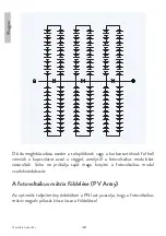
A berendezés földelése

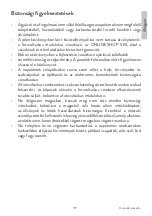
A fotovoltaikus modul keretét, valamint a rögzített berendezés fényvillamos 

rendszerrel táplálható minden szabadon álló, árammentes fém alkatrészét 

a berendezés földelő vezetékéhez (EGC) kell csatlakoztatni az áramütés 

elkerülése érdekében.


A PNI javasolja az összes fotovoltaikus modulkeret földelését, hogy az 

elektromos berendezés és a föld közötti feszültség minden körülmények között 

nulla legyen.

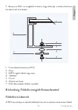
A berendezés megfelelő földelését úgy érik el, hogy minden áramot nem vivő 

fémberendezést csatlakoztatnak, megfelelő méretű EGC (berendezés földelő 

vezeték) használatával az áramütések elkerülése érdekében.


A PNI fotovoltaikus modulok korrózióálló alumínium kerettel rendelkeznek. 

A különböző fémek közötti elektrokémiai hatásból adódó korróziós 

potenciál minimálisra csökken, ha a különböző fémek közötti elektrokémiai 

feszültségpotenciál alacsony.

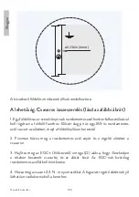
A földelési módszer nem eredményezheti a fémek közvetlen érintkezését a 

fotovoltaikus modul alumínium keretével, ami galvanikus korrózióhoz vezethet.

A fémkombinációk nem haladhatják meg a 0,5 V elektrokémiai 

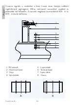
potenciálkülönbséget. A keretsíneken előre fúrt lyukak vannak földelési jellel, 

az alábbi ábra szerint. Ezeket a lyukakat földeléshez kell használni, és nem 

szabad fotovoltaikus modulok felszerelésére használni. Ne készítsen további 

lyukakat a kereten.

Summary of Contents for Green House 370W

Page 1: ...dul Panel solar fotovoltaico monocristalino Panneau solaire photovolta que monocristallin Monokrist lyos fotovoltaikus napelem Pannello solare fotovoltaico monocristallino Monokristallijn fotovolta sc...

Page 2: ...manual 3 BG 25 DE Benutzerhandbuch 50 ES Manual de usuario 73 FR Manuel utilisateur 96 HU Haszn lati utas t s 119 IT Manuale utente 141 NL Handleiding 165 PL Instrukcja obs ugi 186 RO Manual de utiliz...

Page 3: ...talling solar panels keep in mind local legislation and standards on the safety of buildings and electrical installations Photovoltaic systems must be installed only on structurally intact homes and a...

Page 4: ...2 3 5 4 A Junction box B Cable C Connector D Cell E Frame 1 Aluminum frame 2 Glass 3 Encapsulated EVA Ethylene vinyl acetate 4 Photovoltaic cell 5 Black sheet Photovoltaic modules can produce current...

Page 5: ...s manual Never touch electrical connections that are damp without protecting yourself with insulated gloves Transport and handling of solar panels The photovoltaic modules must be transported only in...

Page 6: ...from falling The surfaces of photovoltaic modules are likely to suffer damage that could affect the performance or safety of the photovoltaic module Do not damage or scratch the surface of the PV mod...

Page 7: ...pletely destroyed or the system wiring has been compromised or destroyed In case of fire inform the fire crew and stay away from all elements of the photovoltaic system during and after the fire until...

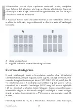
Page 8: ...as shown in the figure below to reduce the risk of lightning induced overvoltages A B A ideal wiring loop B higher risk of lightning induced overvoltage Electrical configuration Under normal condition...

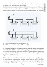
Page 9: ...taic modules must be installed according to the instructions specified by the manufacturer A B A Series connection voltage accumulates B Parallel connection current accumulates The maximum number of p...

Page 10: ...e maximum short circuit current of the photovoltaic module PNI recommends that installers use only sunlight resistant cables dedicated to photovoltaic systems The minimum thread size must be 4 mm2 Cab...

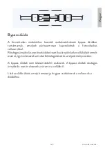
Page 11: ...ovoltaic cells In the case of partial shading the diodes divert the current generated by the unshaded cells thus limiting the heating of the module and the loss of performance Bypass diodes are not ov...

Page 12: ...ors must contact the company from which the photovoltaic modules were purchased Never try to open the junction box of a photovoltaic module yourself Grounding of the PV Array For optimal performance P...

Page 13: ...unding conductor of adequate dimensions to prevent electric shocks PNI photovoltaic modules have an aluminum frame with corrosion resistance The corrosion potential due to the electrochemical action b...

Page 14: ...and then through the earthing hole 2 Lightly tighten the stainless steel nut and locking washer on the screw 3 Bend the EGC ground conductor into an omega shape to fit between the partially installed...

Page 15: ...nductor Option B Grounding by integrated metal structure Grounding methods PNI photovoltaic modules can be grounded by connecting the photovoltaic modules to the metal structure of the panels connecte...

Page 16: ...on the front of the module up to 2400 Pa or 5400 Pa ie wind and snow depending on the module type Mounting structures and other mechanical parts must be designed and approved to withstand the wind and...

Page 17: ...ic modules with a minimum distance of 1 cm between neighboring frames to allow thermal expansion Mounting methods The following mounting methods are available screws or clamps See the figures below Do...

Page 18: ...torque of the screws must be between 14N m and 20N m 1 2 3 4 5 6 7 8 1 PV laminate 2 Aluminum frame 3 Nut 4 Spiral washer 5 Flat washer 6 Support structure 7 Flat washer 8 Screw A B A interior instal...

Page 19: ...clamps applied to the upper part of the long parts of the frame A clamp holds two modules except for the clips at the beginning and end of a row of modules The center line of the clamps must be in lin...

Page 20: ...1 clamp length 40mm B Installation of side clamps on the long frame 2 clamp length 40mm C Installation of side clamps on the short frame 2 clamp length 40mm Type Position L mm Max mechanical load Lon...

Page 21: ...anels Overtime dirtanddustcanaccumulateontheglasssurfaceofthephotovoltaic module reducing its power PNI recommends periodic cleaning of photovoltaic modules to ensure maximum power especially in regio...

Page 22: ...loads However if you want to remove snow to improve strength use a brush to gently remove snow Do not attempt to remove frozen snow or ice from photovoltaic modules Dismantle of solar panels The disma...

Page 23: ...d voltage 34 25 V Vmpp Rated current 10 95 A Impp Open circuit voltage 41 45 V 3 Voc Short circuit current 11 43 A 3 Isc Maximum system voltage 1500 V Series fuses maximum 20 A Degree of fire resistan...

Page 24: ...HOP SRL declares that the PNI Green House 370W monocrystalline photovoltaic solar panel is in accordance with the LVD Directive 2014 35 EU The full text of the EU Declaration of Conformity is availabl...

Page 25: ...25 ONLINESHOP SRL...

Page 26: ...26 A B C D E 1 2 3 5 4 A B C D E 1 2 3 EVA 4 5...

Page 27: ...27 DC 30V...

Page 28: ...28...

Page 29: ...29...

Page 30: ...30 PNI C PNI...

Page 31: ...31 10 A B...

Page 32: ...32 A B STC 1000 W m2 AM 1 5 25 C ISC 1 25 VOC 1 25 PV...

Page 33: ...33 A B A B...

Page 34: ...34 PNI PNI 4 mm2 40 C 90 C 40 mm...

Page 35: ...35...

Page 36: ...36 PV Array PNI...

Page 37: ...37 EGC PNI EGC PNI 0 5V...

Page 38: ...38 0 236in 6mm A 1 M5 2 3 EGC EGC 4 2 3 N m...

Page 39: ...39 5 EGC 1 2 6 3 4 5 7 1 PV 2 3 KEPS 4 5 6 7 EGC...

Page 40: ...40 B PNI C PNI PNI 2400 Pa 2400 Pa 5400 Pa PNI...

Page 41: ...41 0 5 V PNI 10 cm...

Page 42: ...42 1 M8 14N m 20N m 1 2 3 4 5 6 7 8...

Page 43: ...43 1 PV 2 3 4 5 6 7 8 A B B 120 5400 Pa 2400 Pa 50 mm 16N m 24N m...

Page 44: ...44 6 5 2 4 3 1 1 2 3 5 PV 6 7 L L L L L A B C A 1...

Page 45: ...45 40 B 2 40mm C 2 40mm L mm 1 350 470 5400Pa 2400Pa 2 350 470 2400Pa 2400Pa 0 250 1600Pa 1600Pa 1 0 250 1600Pa 1600Pa PNI...

Page 46: ...46 PNI PNI PV PH6 9 690 kPa PNI...

Page 47: ...47 PNI 10 Isc Voc Pmax 1000 W m2 AM 1 5 25 C 370 0 W 3 0 5 W 34 25 V Vmpp 10 95 A Impp 41 45 V 3 Voc 11 43 A 3 Isc 1500 V 20 A C...

Page 48: ...48 A B A B Sectiune transversala a cadrului...

Page 49: ...49 SC ONLINESHOP SRL PNI Green House 370W LVD 2014 35 https www mypni eu products 8454 download certifications...

Page 50: ...ei der Installation von Sonnenkollektoren die rtlichen Gesetze und Normen bez glich der Sicherheit von Bau und Elektroinstallationen Photovoltaikanlagen d rfen nur auf baulich intakten H usern install...

Page 51: ...em Isoliermaterial mit einer starren Glasoberfl che und einem isolierten Substrat gekapselt sind Der Laminataufbau wird von einem Aluminiumrahmen getragen der auch zur Montage des Moduls dient A B C D...

Page 52: ...he Anschl sse k nnen auch Lichtb gen und Stromschl ge verursachen Halten Sie die Anschl sse trocken und sauber und vergewissern Sie sich dass sie in gutem Zustand sind Stecken Sie niemals Metallgegens...

Page 53: ...onPhotovoltaikmodulenaufhartenOberfl chen vorsichtig und sichern Sie diese gegen Herunterfallen Glasbruch kann zu Personensch den f hren Glasbruch Photovoltaikmodule k nnen nicht repariert werden und...

Page 54: ...einschlie lich des Rahmens auf Bauen Sie die Photovoltaikmodule zu Ihrer eigenen Sicherheit nicht auseinander oder ver ndern Sie sie in keiner Weise Dies kann die Leistung beeintr chtigen oder irrepa...

Page 55: ...vollst ndig zerst rt oder die Anlagenverkabelung beeintr chtigt oder zerst rt wurden Informieren Sie im Brandfall die Feuerwehr und halten Sie sich w hrend und nach dem Brand von allen Elementen der...

Page 56: ...roduktion der Photovoltaik Module zu erh hen Blitzschutz wird f r Photovoltaikanlagen empfohlen die an Orten mit hoher Blitzwahrscheinlichkeit installiert werden sollen Bei indirektem Blitzeinschlag k...

Page 57: ...niedrigste am Installationsort erfasste Umgebungstemperatur die Nennspannung der Komponenten den Nennstrom des Leiters die Abmessungen der Sicherungen und die Gr e der an den PV Ausgang angeschlossen...

Page 58: ...die an den Enden mit Steckern ausgestattet sind Der Pluspol hat einen Mutterstecker w hrend der Minuspol einen Stecker hat Die Modulverkabelung ist f r serielle Verbindungen vorgesehen kann aber auch...

Page 59: ...er dass alle Anschl sse vollst ndig angeschlossen und verriegelt sind Die Module d rfen nicht mit Steckern unterschiedlicher Hersteller oder unterschiedlicher Bauart verbunden werden Bypass Diode Die...

Page 60: ...nal an das Unternehmen wenden von dem die Photovoltaikmodule gekauft wurden Versuchen Sie niemals die Anschlussdose eines Photovoltaikmoduls selbst zu ffnen Erdung der Photovoltaik Matrix PV Array F r...

Page 61: ...omschl ge zu vermeiden PNI Photovoltaikmodule haben einen korrosionsbest ndigen Aluminiumrahmen Das Korrosionspotential aufgrund der elektrochemischen Wirkung zwischen verschiedenen Metallen in Kontak...

Page 62: ...lstahlschraube durch die Unterlegscheibe und dann durch das Erdungsloch 2 Ziehen Sie die Edelstahlmutter und die Sicherungsscheibe leicht an der Schraube an 3 Biegen Sie den EGC Erdungsleiter in eine...

Page 63: ...niumrahmen des Moduls zu vermeiden 1 2 6 3 4 5 7 1 Photovoltaik Laminat PV 2 Nuss 3 KEPS Sicherungsscheibe oder Mutter 4 Schutz 5 Schraube 6 Aluminiumrahmen 7 EGC Ger teerdungsleiter Option B Erdung d...

Page 64: ...tung auf der R ckseite des Moduls bis zu 2400 Pa dh Windlast und eine maximale statische Belastung auf der Vorderseite des Moduls bis zu 2400 Pa oder 5400 Pa dh Wind und Schnee zertifiziert je nach Mo...

Page 65: ...ovoltaikmodul zu k hlen Installieren Sie Photovoltaikmodule mit einem Mindestabstand von 1 cm zwischen benachbarten Rahmen um die W rmeausdehnung zu erm glichen Montagemethoden Folgende Befestigungsar...

Page 66: ...der L ngsteile des Rahmens mit M8 Edelstahlschrauben Muttern und Unterlegscheiben montiert werden Das Anzugsdrehmoment der Schrauben muss zwischen 14N m und 20N m liegen 1 2 3 4 5 6 7 8 1 PV Laminat...

Page 67: ...sind eine akzeptierteMontagemethode DieModulem ssenmitKlemmenamoberenTeil der L ngsteile des Rahmens befestigt werden Eine Klemme h lt zwei Module mit Ausnahme der Klemmen am Anfang und am Ende einer...

Page 68: ...Klemmen am langen Rahmen 1 Klemmenl nge 40mm B Montage der seitlichen Klemmen am langen Rahmen 2 Klemmenl nge 40mm C Montage der seitlichen Klemmen am kurzen Rahmen 2 Klemmenl nge 40mm Typ Position L...

Page 69: ...hattet Die Befestigungs und Erdungskomponenten sind gut befestigt ohne Korrosion Beobachtete Fehler m ssen sofort behoben werden Sonnenkollektoren reinigen Auf der Glasoberfl che des Photovoltaikmodul...

Page 70: ...Chemikalien Verwenden Sie keine aggressiven Werkzeuge oder scheuernden Materialien die die Glasoberfl che zerkratzen oder besch digen k nnten Die Nichteinhaltung dieser Anforderungen kann die Leistun...

Page 71: ...Voc und Pmax unter Standardtestbedingungen Bestrahlung von 1000 W m2 AM 1 5 Spektrum und eine Zelltemperatur von 25 C Nennleistung 370 0 W 3 Leistungsauswahl 0 5 W Nennspannung 34 25 V Vmpp Nennstrom...

Page 72: ...rmit tserkl rung SC ONLINESHOP SRL erkl rt dass das monokristalline Photovoltaik Solarmodul PNI Green House 370W der LVD Richtlinie 2014 35 EU entspricht Den vollst ndigen Text der EU Konformit tserkl...

Page 73: ...en cuenta las leyes y normas locales con respecto a la seguridad de la construcci n y las instalaciones el ctricas Los sistemas fotovoltaicos deben instalarse solo en viviendas estructuralmente intact...

Page 74: ...ulo A B C D E 1 2 3 5 4 A Caja de conexiones B Cable C Conector D Celda E Marco 1 Marco de aluminio 2 Vidrio 3 EVA encapsulado etileno acetato de vinilo 4 Celda fotovoltaica 5 Hoja negra Los m dulos f...

Page 75: ...est n usando el equipo de protecci n adecuado Evite manipular los m dulos fotovoltaicos cuando est n mojados a menos que los limpie primero de acuerdo con las instrucciones de este manual Nunca toque...

Page 76: ...correas de sujeci n si se proporcionan Retire los m dulos fotovoltaicos uno por uno desliz ndolos hacia arriba por el canal en el paquete vea la figura a continuaci n Puede ser necesario fijar los m d...

Page 77: ...car la aparici n inesperada de un arco el ctrico durante el funcionamiento Para reducir el riesgo de incendio los m dulos fotovoltaicos no deben instalarse cerca de l quidos gases inflamables o lugare...

Page 78: ...la lluvia Elsombreadoparcialocompletodeunm dulopuedereducirsignificativamente el rendimiento del sistema Recomendamos minimizar la cantidad de sombra durante todo el a o para aumentar la cantidad de...

Page 79: ...n el lugar de instalaci n para determinar la tensi n nominal de los componentes la corriente nominal del conductor las dimensiones de los fusibles y el tama o de los controles conectados a la salida f...

Page 80: ...equipados con dos cables de salida resistentes a la luz solar equipados con conectores en los extremos El terminal positivo tiene un conector madre mientras que el terminal negativo tiene un conector...

Page 81: ...eados Los m dulos no deben interconectarse utilizando conectores de diferentes fabricantes o de diferentes tipos Diodo de derivaci n Las cajas de conexiones utilizadas con los m dulos fotovoltaicos co...

Page 82: ...e en contacto con la empresa a la que adquirieron los m dulos fotovoltaicos Nunca intente abrir usted mismo la caja de conexiones de un m dulo fotovoltaico Puesta a tierra de la matriz fotovoltaica PV...

Page 83: ...ensiones adecuadas para evitar descargas el ctricas Los m dulos fotovoltaicos PNI tienen un marco de aluminio con resistencia a la corrosi n El potencial de corrosi n debido a la acci n electroqu mica...

Page 84: ...inoxidable Primero inserte un tornillo de acero inoxidable M5 a trav s de la arandela y luego a trav s del orificio de conexi n a tierra 2 Apriete ligeramente la tuerca de acero inoxidable y la arande...

Page 85: ...5 Dirija el EGC al tama o apropiado para evitar el contacto con el marco de aluminio del m dulo 1 2 6 3 4 5 7 1 Laminado fotovoltaico PV 2 Tuerca 3 Arandela o tuerca de bloqueo KEPS 4 Protecci n 5 Tor...

Page 86: ...siempre que est n certificados para la puesta a tierra de m dulos fotovoltaicos y los dispositivos se instalen de acuerdo con las instrucciones especificadas por el fabricante Instalaci n mec nica Los...

Page 87: ...montar con orientaci n horizontal o vertical como se muestra en la figura siguiente Para cumplir con la clase de resistencia al fuego la distancia entre la superficie frontal del m dulo fotovoltaico v...

Page 88: ...marco para que se deforme Montaje con tornillos los m dulos deben montarse utilizando los orificios de montaje en la parte posterior de las partes largas del marco utilizando tornillos tuercas y arand...

Page 89: ...demontajeaceptado Losm dulosdebenfijarsemedianteabrazaderasaplicadas en la parte superior de las partes largas del marco Una abrazadera sostiene dos m dulos excepto los clips al principio y al final d...

Page 90: ...5 2 4 3 1 1 Marco de aluminio 2 Arandela plana 3 Carril de montaje 5 Laminado fotovoltaico 6 Tuerca 7 Tornillo L L L L L A B C Posicionamiento de la abrazadera A Instalaci n de abrazaderas laterales e...

Page 91: ...ares PNI recomienda que los sistemas fotovoltaicos sean revisados peri dicamente por un instalador u otra persona calificada El prop sito de la inspecci n del sistema fotovoltaico es garantizar que to...

Page 92: ...n cepillo suave usando agua sin detergente PH6 9 con una presi n recomendada de menos de 690 kPa que es t pica para la mayor a de los sistemas de suministro de agua El agua con un alto contenido de mi...

Page 93: ...posel ctricosenergizados Elimine los desechos de los sistemas de votaci n de acuerdo con la legislaci n local Caracter sticas electricas Losvaloresdelaetiquetadeidentificaci nsonvaloresmedios Lascarac...

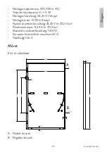
Page 94: ...Manual de usuario Espa ol 94 Talla Vista frontal y lateral A B A Agujeros en el suelo B Agujeros de montaje Secci n transversal del marco...

Page 95: ...INESHOP SRL declara que el panel solar fotovoltaico monocristalino PNI Green House370WcumpleconlaDirectivaLVD2014 35 UE EltextocompletodelaDeclaraci n de conformidad de la UE est disponible en la sigu...

Page 96: ...es concernant la s curit de la construction et des installations lectriques Les syst mes photovolta ques doivent tre install s uniquement sur des maisons dont la structure est intacte et capables de s...

Page 97: ...sul es dans un mat riau isolant avec une surface en verre rigide et un substrat isol L ensemble stratifi est soutenu par un cadre en aluminium qui est galement utilis pour monter le module A B C D E 1...

Page 98: ...ctriques sous charge Des connexions erron es peuvent galement provoquer des arcs et des d charges lectriques Gardez les connecteurs secs et propres et assurez vous qu ils sont en bon tat de fonctionne...

Page 99: ...mber ou posez d objets lourds dessus Soyez prudent lorsque vous placez des modules photovolta ques sur des surfaces dures et s curisez les contre les chutes Le verre bris peut entra ner des blessures...

Page 100: ...votre s curit ne d montez ou ne modifiez en aucun cas les modules photovolta ques Cela peut affecter les performances ou causer des dommages irr parables et annulera toute garantie applicable Si les...

Page 101: ...age du syst me a t compromis ou d truit En cas d incendie informez les pompiers et restez l cart de tous les l ments de l installation photovolta que pendant et apr s l incendie jusqu ce que les mesur...

Page 102: ...ntit d nergie produite par les modules photovolta ques La protection contre la foudre est recommand e pour les syst mes photovolta ques installer dans des endroits forte probabilit de foudre Des tensi...

Page 103: ...a taille des commandes connect es la sortie PV La tension s accumule lorsque les modules photovolta ques sont connect s en s rie et le courant s accumule lorsque les modules photovolta ques sont conne...

Page 104: ...soleil munis de connecteurs aux extr mit s La borne positive a un connecteur m re tandis que la borne n gative a un connecteur m le Le c blage du module est destin aux connexions s rie mais peut galem...

Page 105: ...nterconnect s l aide de connecteurs de fabricants diff rents ou de types diff rents Diode de d rivation Les bo tes de jonction utilis es avec les modules photovolta ques contiennent des diodes de d ri...

Page 106: ...la soci t aupr s de laquelle les modules photovolta ques ont t achet s N essayez jamais d ouvrir vous m me la bo te de jonction d un module photovolta que Mise la terre de la matrice photovolta que PV...

Page 107: ...re de l quipement de dimensions ad quates pour viter les chocs lectriques Les modules photovolta ques PNI ont un cadre en aluminium r sistant la corrosion Le potentiel de corrosion d l action lectroch...

Page 108: ...dable Ins rez d abord une vis en acier inoxydable M5 dans la rondelle puis dans le trou de mise la terre 2 Serrez l g rement l crou en acier inoxydable et la rondelle de blocage sur la vis 3 Pliez l E...

Page 109: ...ule 1 2 6 3 4 5 7 1 Stratifi photovolta que PV 2 crou 3 Rondelle ou crou frein KEPS 4 Prot ger 5 Vis 6 Cadre en aluminium 7 EGC conducteur de mise la terre de l quipement Option B Mise la terre par st...

Page 110: ...our une charge statique maximale l arri re du module jusqu 2400 Pa c est dire la charge du vent et une charge statique maximale l avant du module jusqu 2400 Pa ou 5400 Pa c est dire le vent et la neig...

Page 111: ...e refroidir le module photovolta que Installer des modules photovolta ques avec une distance minimalede1cmentrelescadresvoisinspourpermettreladilatationthermique M thodes de montage Les m thodes de mo...

Page 112: ...n au dos des parties longues du ch ssis l aide de vis crous et rondelles en acier inoxydable M8 Le couple de serrage des vis doit tre compris entre 14N m et 20N m 1 2 3 4 5 6 7 8 1 Stratifi PV 2 Cadre...

Page 113: ...ontage accept e Les modules doivent tre fix s l aide de pinces appliqu es sur la partie sup rieure des parties longues du cadre Une pince maintient deux modules l exception des clips au d but et la fi...

Page 114: ...rales sur le cadre long 1 longueur pince 40mm B Installation des pinces lat rales sur le cadre long 2 longueur pince 40mm C Installation des pinces lat rales sur le cadre court 2 longueur pince 40mm...

Page 115: ...terre sont bien fix s sans corrosion Les d fauts constat s doivent tre corrig s imm diatement Nettoyage de panneaux solaires Au fil du temps la salet et la poussi re peuvent s accumuler sur la surfac...

Page 116: ...lisez pas d outils agressifs ou de mat riaux abrasifs qui pourraient rayer ou endommager la surface en verre Le non respect de ces exigences peut nuire aux performances du module photovolta que Les mo...

Page 117: ...itions de test standard irradiation de 1000 W m2 spectre AM 1 5 et une temp rature de cellule de 25 C Puissance nominale 370 0 W 3 S lection de la puissance 0 5 W Tension nominale 34 25 V Vmpp Courant...

Page 118: ...nformit UE simplifi e SC ONLINESHOP SRL d clare que le panneau solaire photovolta que monocristallin PNI Green House 370W est conforme la directive LVD 2014 35 UE Le texte int gral de la d claration d...

Page 119: ...el tt a helyi t rv nyeket s szabv nyokat az p tkez s s az elektromos berendez sek biztons g ra vonatkoz an Afotovoltaikusrendszereketcsakszerkezetilegs rtetlenotthonokraszabad felszerelni s k pesek el...

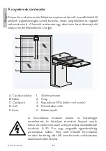
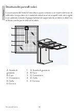
Page 120: ...l A B C D E 1 2 3 5 4 A Csatlakoz doboz B K bel C Csatlakoz D Cell E Keret 1 Alum nium keret 2 veg 3 Kapszul zott EVA etil n vinil acet t 4 Fotovoltaikus cella 5 Fekete leped A fotovoltaikus modulok...

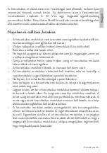
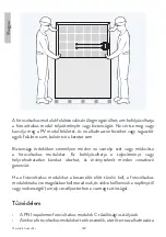
Page 121: ...ltaikus modulok nehezek s vatosan kell b nni vel k A fotovoltaikus modulokat a keretnek kell kezelnie soha ne haszn lja a csatlakoz dobozt vagy a k beleket a panelek kezel s re Ne fejtsen ki mechanika...

Page 122: ...on ne szerelje sz t vagy m dos tsa a fotovoltaikus modulokat Ez befoly solhatja a teljes tm nyt vagy helyrehozhatatlan k rokat okozhat s rv nytelen t minden vonatkoz garanci t Ha a fotovoltaikus modul...

Page 123: ...a sz ks ges int zked seket a fotovoltaikus rendszer biztons ga rdek ben Szerel si korl toz sok A PNI fotovoltaikus modulokat p leteken talajon vagy m s fotovoltaikus modulokhoz alkalmas szerkezeteken...

Page 124: ...ozta t lfesz lts g kock zata Elektromos konfigur ci Norm l k r lm nyek k z tt a fotovoltaikus modulok olyan felt telekkel szembes lhetnek amelyek nagyobb ramot vagy fesz lts get termelnek mint a stand...

Page 125: ...koz s ram felhalmoz dik A sorba kapcsolhat fotovoltaikus modulok maxim lis sz m t a vonatkoz el r soknak megfelel en kell kisz m tani gy hogy a fotovoltaikus modul s az sszes t bbi egyen ram elektromo...

Page 126: ...nie K bel h m rs klet tartom ny 40 C 90 C A k beleket gy kell a tart szerkezethez r gz teni hogy elker lj k a k bel vagy a modul mechanikai s r l s t Ne hajl tsa meg a k beleket 40 mm n l kisebb hajl...

Page 127: ...voltaikus cellasorokkal R szleges rny kol seset nadi d kelvezetikaz rny kolatlancell k ltaltermelt ramot gy korl tozz k a modul felmeleged s t s a teljes tm nyveszt st A bypass di d k nem t l ramv del...

Page 128: ...kapcsolatot azzal a c ggel amelyt l a fotovoltaikus modulokat v s rolt k Soha ne pr b lja saj t maga kinyitni a fotovoltaikus modul csatlakoz doboz t A fotovoltaikus m trix f ldel se PV Array Az optim...

Page 129: ...berendez s f ldel vezet k haszn lat val az ram t sek elker l se rdek ben A PNI fotovoltaikus modulok korr zi ll alum nium kerettel rendelkeznek A k l nb z f mek k z tti elektrok miai hat sb l ad d ko...

Page 130: ...El sz r dugjon t egy M5 s rozsdamentes ac l csavart az al t ten majd a f ldel ny l son kereszt l 2 Finoman h zza meg a rozsdamentes ac l any t s a r gz t al t tet a csavaron 3 Hajl tsa meg az EGC t f...

Page 131: ...vel val rintkez st 1 2 6 3 4 5 7 1 Fotovoltaikus lamin tum PV 2 Anya 3 KEPS r gz t al t t vagy anya 4 V delem 5 Csavar 6 Alum nium keret 7 EGC berendez s f ldel vezet k B lehet s g F ldel s integr lt...

Page 132: ...n 2400 Pa ig terjed maxim lis statikus terhel sre azaz sz lterhel s s a modul el ls r sz nek maxim lis statikus terhel s re 2400 Pa vagy 5400 Pa ig azaz sz l s h tan s tottak a modul t pus t l f gg e...

Page 133: ...hogy a l g raml s leh tse a fotovoltaikus modult Szerelje be a fotovoltaikus modulokat legal bb 1 cm t vols gra a szomsz dos keretek k z tt hogy lehet v tegye a h t gul st Szerel si m dok A k vetkez r...

Page 134: ...at r gz t furatok seg ts g vel M8 as nemesac l csavarokkal any kkal s al t tekkel kell felszerelni A csavarok megh z si nyomat k nak 14N m s 20N m k z tt kell lennie 1 2 3 4 5 6 7 8 1 PV lamin lt 2 Al...

Page 135: ...si m d A modulokat a keret hossz r szeinek fels r sz re r gz tett bilincsekkel kell r gz teni Egy bilincs k t modult tart kiv ve a modulsor elej n s v g n l v kapcsokat A bilincsek k z pvonal nak egy...

Page 136: ...hossza 40 mm B Oldals bilincsek felszerel se a hossz keretre 2 bilincs hossza 40 mm C Oldals bilincsek felszerel se a r vid keretre 2 bilincs hossza 40 mm T pus Poz ci L mm Maxim lis mechanikai terhel...

Page 137: ...t sa Id velszennyez d s sporhalmoz dhatfelafotovoltaikusmodul vegfel let n ami cs kkenti annak teljes tm ny t A PNI javasolja a fotovoltaikus modulok id szakos tiszt t s t a maxim lis teljes tm ny bi...

Page 138: ...nek Ha azonban a havat szeretn elt vol tani az er n vel se rdek ben kef vel vatosan t vol tsa el a havat Ne pr b lja meg elt vol tani a fagyott havat vagy jeget a fotovoltaikus modulokr l A fotovoltai...

Page 139: ...W N vleges fesz lts g 34 25 V Vmpp N vleges ram 10 95 A Impp Nyitott ramk ri fesz lts g 41 45 V 3 Voc R vidz rlati ram 11 43 A 3 Isc Maxim lis rendszerfesz lts g 1500 V Sorozatos biztos t kok maximum...

Page 140: ...nyilatkozat Az SC ONLINESHOP SRL kijelenti hogy a PNI Green House 370W monokrist lyos fotovoltaikus napelem megfelel a 2014 35 EU LVD ir nyelvnek Az EU megfelel s gi nyilatkozat teljes sz vege az al b...

Page 141: ...ari tenere presente le leggi e gli standard locali relativi alla sicurezza della costruzione e degli impianti elettrici Gli impianti fotovoltaici devono essere installati solo su abitazioni struttural...

Page 142: ...solari incapsulate in un materiale isolante con una superficie di vetro rigida e un substrato isolante Il gruppo laminato supportato da un telaio in alluminio utilizzato anche per montare il modulo A...

Page 143: ...urarsi che siano in buone condizioni Non inserire mai oggetti metallici nei connettori e non modificarli in nessun caso per garantire un collegamento elettrico Non toccare o maneggiare moduli fotovolt...

Page 144: ...non possono essere riparati e non devono essere utilizzati I moduli fotovoltaici rotti o danneggiati devono essere maneggiati con cura e smaltiti secondo le normative locali Per disimballare i moduli...

Page 145: ...i sono dispositivi che generano elettricit che possono influire sulla sicurezza antincendio di un edificio L uso di metodi di installazioneimpropriopartidifettosepu portareallacomparsainaspettata di u...

Page 146: ...on un angolo di inclinazione di almeno 10 gradi per consentire l autopulizia sotto i temporali L ombreggiaturaparzialeocompletadiunmodulopu ridurresignificativamente le prestazioni del sistema Si cons...

Page 147: ...fattore fino a 1 25 in base alla temperatura ambiente pi bassa registrata nel luogo di installazione per determinare la tensione nominale dei componenti la corrente nominale del conduttore le dimensio...

Page 148: ...onenti elettrici in corrente continua non venga superata nel funzionamento a circuito aperto al temperatura minima prevista nella posizione dell impianto fotovoltaico Un dispositivo di protezione da s...

Page 149: ...rvallo di temperatura del cavo 40 C 90 C I cavi devono essere fissati alla struttura di montaggio in modo da evitare danni meccanici al cavo o al modulo Non piegare i cavi con un raggio di curvatura i...

Page 150: ...giamento parziale i diodi deviano la corrente generata dalle celle non ombreggiate limitando cos il riscaldamento del modulo e la perdita di prestazioni I diodi di bypass non sono dispositivi di prote...

Page 151: ...fotovoltaici Non tentare mai di aprire da soli la scatola di giunzione di un modulo fotovoltaico Messa a terra della matrice fotovoltaica PV Array Per prestazioni ottimali PNI consiglia di collegare...

Page 152: ...e elettriche I moduli fotovoltaici PNI hanno un telaio in alluminio con resistenza alla corrosione Ilpotenzialedicorrosionedovutoall azioneelettrochimicatradiversi metalli a contatto ridotto al minimo...

Page 153: ...o di messa a terra 2 Serrare leggermente il dado in acciaio inossidabile e la rondella di bloccaggio sulla vite 3 Piegare l EGC conduttore di terra a forma di omega per adattarlo tra la testa della vi...

Page 154: ...fotovoltaici e devono essere installati secondo le istruzioni specificate dei rispettivi produttori Opzione C dispositivi di messa a terra aggiuntivi di terze parti I moduli fotovoltaici PNI possono e...

Page 155: ...espansione termica Il metodo di montaggio non deve comportare il contatto diretto dei vari metalli con il telaio in alluminio del modulo fotovoltaico che porter alla corrosione galvanica Le combinazi...

Page 156: ...todi di montaggio Sono disponibili i seguenti metodi di montaggio viti o morsetti Vedere le figure di seguito Non modificare i fori di montaggio esistenti n crearne di nuovi Non applicare una pression...

Page 157: ...ure di montaggio di pannelli fotovoltaici sono un metodo di montaggio accettato I moduli devono essere fissati mediante fascette applicate sulla parte superiore delle parti lunghe del telaio Un morset...

Page 158: ...6 5 2 4 3 1 1 Telaio in alluminio 2 Rondella piana 3 Binario di montaggio 5 Laminato fotovoltaico 6 Dado 7 Vite L L L L L A B C Posizionamento del morsetto A Installazione dei morsetti laterali sul t...

Page 159: ...PNI consiglia di far controllare periodicamente gli impianti fotovoltaici da un installatore o altra persona qualificata Lo scopo dell ispezione dell impianto fotovoltaico garantire che tutti i compon...

Page 160: ...izzando acqua priva di detergenti PH6 9 con una pressione consigliata inferiore a 690 kPa tipica per la maggior parte dei sistemi di approvvigionamento idrico L acqua ad alto contenuto di minerali pu...

Page 161: ...chiature elettriche sotto tensione Smaltire i rifiuti dei sistemi di voto secondo la legislazione locale Caratteristiche elettriche I valori sull etichetta di identificazione sono valori medi Le carat...

Page 162: ...Manuale dell utente Italiano 162 Dimensione Vista frontale e laterale A B A Fori a terra B Fori di montaggio Sezione trasversale del telaio...

Page 163: ...ESHOP SRL declara ca Panou solar fotovoltaic PNI Green House 370W monocristalin este in conformitate cu Directiva LVD 2014 35 EU Textul integral al declaratiei UE de conformitate este disponibil la ur...

Page 164: ...zonnepanelen rekening met de lokale wetten en normen met betrekking tot de veiligheid van constructies en elektrische installaties Fotovolta sche systemen mogen alleen worden ge nstalleerd op structu...

Page 165: ...e te monteren A B C D E 1 2 3 5 4 A Aansluitdoos B Kabel C Connector D cel E Kader 1 Aluminium frame 2 Glas 3 Ingekapseld EVA ethyleenvinylacetaat 4 Fotovolta sche cel 5 Zwart blad Fotovolta sche modu...

Page 166: ...tenzij de fotovolta sche modules eerst zijn losgekoppeld en geschikte beschermende uitrusting dragen Vermijd het hanteren van fotovolta sche modules als ze nat zijn tenzij u ze eerst schoonmaakt volge...

Page 167: ...e modules uit de originele verpakking te halen verwijdert u eerst het deksel van de doos na het verwijderen van de bevestigingsriemen indien aanwezig Verwijder de fotovolta sche modules n voor n door...

Page 168: ...gebruik van onjuiste installatiemethoden of defecte onderdelen kan leiden tot het onverwachte optreden van een elektrische boog tijdens het gebruik Om het risico op brand te verminderen mogen fotovolt...

Page 169: ...genbuien mogelijk te maken Gedeeltelijke of volledige beschaduwing van een module kan de systeemprestaties aanzienlijk verminderen We raden aan om de hoeveelheid schaduw het hele jaar door te minimali...

Page 170: ...rd op de laagste omgevingstemperatuur geregistreerd op de installatielocatie om te bepalen de nominale spanning van de componenten de nominale stroom van de geleider de afmetingen van de zekeringen en...

Page 171: ...uitgerust met twee uitgangskabels bestand tegen zonlicht uitgerust met connectoren aan de uiteinden De positieve pool heeft een moederconnector terwijl de negatieve pool een mannelijke connector heef...

Page 172: ...grendeld De modules mogen niet onderling worden verbonden met connectoren van verschillende fabrikanten of van verschillende typen Bypass diode De aansluitdozen die bij de fotovolta sche modules worde...

Page 173: ...s contact opnemen met het bedrijf waar de fotovolta sche modules werden gekocht Probeer nooit zelf de aansluitdoos van een fotovolta sche module te openen Aarding van de fotovolta sche matrix PV Array...

Page 174: ...de grootte om elektrische schokken te voorkomen PNI fotovolta sche modules hebben een aluminium frame dat bestand is tegen corrosie Het corrosiepotentieel als gevolg van de elektrochemische werking tu...

Page 175: ...de ring en vervolgens door het aardingsgat 2 Draai de roestvrijstalen moer en borgring met tanden op de schroef licht vast 3 BuigdeEGC aardgeleider ineenomega vorm omtussendegedeeltelijk ge nstalleer...

Page 176: ...der van apparatuur Optie B Aarding door ge ntegreerde metalen structuur Aardingsmethoden PNI fotovolta sche modules kunnen worden geaard door de fotovolta sche modules aan te sluiten op de metalen str...

Page 177: ...sche belasting aan de voorkant van de module tot 2400 Pa of 5400 Pa dwz wind en sneeuw afhankelijk van het moduletype Montageconstructies en andere mechanische onderdelen moeten zodanig zijn ontworpen...

Page 178: ...e luchtstroom ook de fotovolta sche module koelen Installeer fotovolta sche modules met een minimale afstand van 1 cm tussen aangrenzende frames om thermische uitzetting mogelijk te maken Montagemetho...

Page 179: ...aan de achterkant van de lange delen van het frame met behulp van M8 roestvrijstalen schroeven moeren en ringen Het aanhaalmoment van de schroeven moet tussen 14N m en 20N m liggen 1 2 3 4 5 6 7 8 1...

Page 180: ...ules moeten worden bevestigd met behulp van klemmen die op het bovenste deel van de lange delen van het frame worden aangebracht Een klem houdt twee modules vast behalve de clips aan het begin en eind...

Page 181: ...klemlengte 40 mm B Installatie van zijklemmen op het lange frame 2 klemlengte 40 mm C Installatie van zijklemmen op het korte frame 2 klemlengte 40 mm Type Positie L mm Maximale mechanische belasting...

Page 182: ...holpen Zonnepanelen schoonmaken Na verloop van tijd kunnen vuil en stof zich ophopen op het glasoppervlak van de fotovolta sche module waardoor het vermogen afneemt PNI beveelt periodiekereinigingvanf...

Page 183: ...en Het niet naleven van deze vereisten kan de prestaties van de fotovolta sche module nadelig be nvloeden PNI fotovolta sche modules zijn ontworpen om zware sneeuwbelasting te weerstaan Als u echter s...

Page 184: ...Pmax in standaard testomstandigheden instraling van 1000 W m2 AM 1 5 spectrum en een temperatura a celulei de 25 C Nominaal vermogen 370 0 W 3 Vermogensselectie 0 5 W Nominale spanning 34 25 V Vmpp N...

Page 185: ...erklaring SC ONLINESHOP SRL verklaart dat het PNI Green House 370W monokristallijne fotovolta sche zonnepaneel in overeenstemming is met de LVD richtlijn 2014 35 EU De volledige tekst van de EU confor...

Page 186: ...ych nale y pami ta o lokalnych przepisach i normach dotycz cych bezpiecze stwa konstrukcji i instalacji elektrycznych Systemy fotowoltaiczne musz by instalowane tylko w domach o nienaruszonej konstruk...

Page 187: ...zatopionych w materiale izolacyjnym o sztywnej szklanejpowierzchniiizolowanympod o u Zesp laminatujestpodtrzymywany przez aluminiow ram kt ra s u y r wnie do monta u modu u A B C D E 1 2 3 5 4 A Skrzy...

Page 188: ...cze elektrycznych pod obci eniem Niew a ciwe po czenia mog r wnie powodowa uki i pora enia pr dem Utrzymuj z cza w stanie suchym i czystym oraz upewnij si e s w dobrym stanie Nigdy nie wk adaj metalow...

Page 189: ...i nie k ad na nich ci kich przedmiot w Zachowaj ostro no podczas uk adania modu w fotowoltaicznych na twardych powierzchniach i zabezpiecz je przed upadkiem P kni te szk o mo e prowadzi do obra e cia...

Page 190: ...n powierzchni w tym ram Dla w asnego bezpiecze stwa nie nale y w aden spos b demontowa ani modyfikowa modu w fotowoltaicznych Mo e to wp yn na wydajno lub spowodowa nieodwracalne uszkodzenia i uniewa...

Page 191: ...one od falownika zosta y cz ciowo lub ca kowicie zniszczone lub okablowanie systemu zosta o naruszone lub zniszczone W przypadku po aru poinformuj stra po arn i trzymaj si z dala od wszystkich element...

Page 192: ...ii wytwarzanej przez modu y fotowoltaiczne Ochrona odgromowa jest zalecana w przypadku instalacji fotowoltaicznych w miejscach o du ym prawdopodobie stwie wy adowania atmosferycznego Wysokie napi cia...

Page 193: ...toczenia zarejestrowan w miejscu instalacji aby okre li napi cie znamionowe komponent w pr d znamionowy przewodu wymiary bezpiecznik w i wielko element w steruj cych pod czonych do wyj cia PV Napi cie...

Page 194: ...dwa kable wyj ciowe odporne na dzia anie promieni s onecznych wyposa one na ko cach w z cza Zacisk dodatni ma z cze matki a zacisk ujemny ma z cze m skie Okablowanie modu u jest przeznaczone do po cze...

Page 195: ...czone i zablokowane Modu w nie wolno czy za pomoc z czy r nych producent w lub r nych typ w Dioda obej ciowa Puszki po czeniowe stosowane z modu ami fotowoltaicznymi zawieraj diody bocznikuj ce po czo...

Page 196: ...towa si z firm od kt rej zakupiono modu y fotowoltaiczne Nigdy nie pr buj samodzielnie otwiera puszki po czeniowej modu u fotowoltaicznego Uziemienie matrycy fotowoltaicznej PV Array W celu uzyskania...

Page 197: ...cego urz dzenia o odpowiednim rozmiarze aby zapobiec pora eniom elektrycznym Modu y fotowoltaiczne PNI posiadaj aluminiow ram o odporno ci na korozj Potencja korozyjny wynikaj cy z oddzia ywania elek...

Page 198: ...zewnej Najpierw w rub ze stali nierdzewnej M5 przez podk adk a nast pnie przez otw r uziemiaj cy 2 Lekko dokr nakr tk ze stali nierdzewnej i podk adk zabezpieczaj c z bami na rubie 3 Zagnij EGC przew...

Page 199: ...unikn kontaktu z aluminiow ram modu u 1 2 6 3 4 5 7 1 Laminat fotowoltaiczny PV 2 Orzech 3 Podk adka lub nakr tka blokuj ca KEPS 4 Ochrona 5 ruba 6 Rama aluminiowa 7 EGC przew d uziemiaj cy urz dzeni...

Page 200: ...rtyfikowane dla maksymalnego obci enia statycznego z ty u modu u do 2400 Pa tj obci enia wiatrem i maksymalnego obci enia statycznego z przodu modu u do 2400 Pa lub 5400 Pa tj wiatru i niegu w zale no...

Page 201: ...odzenie modu u fotowoltaicznego przez przep yw powietrza Zainstaluj modu y fotowoltaiczne z minimaln odleg o ci 1 cm mi dzy s siednimi ramami aby umo liwi rozszerzalno ciepln Metody monta u Dost pne...

Page 202: ...owych z ty u d ugich cz ci ramy za pomoc rub nakr tek i podk adek ze stali nierdzewnej M8 Moment dokr cania rub musi wynosi od 14 N m do 20 N m 1 2 3 4 5 6 7 8 1 Laminat PV 2 Rama aluminiowa 3 Orzech...

Page 203: ...monta owych paneli fotowoltaicznych s akceptowan metod monta u Modu y nale y mocowa za pomoc zacisk w na o onych na g rn cz d ugich cz ci ramy Zacisk trzyma dwa modu y z wyj tkiem zacisk w na pocz tk...

Page 204: ...e d ugiej 1 d ugo zacisku 40mm B Monta zacisk w bocznych na ramie d ugiej 2 d ugo zacisku 40mm C Monta zacisk w bocznych na ramie kr tkiej 2 d ugo zacisku 40mm Rodzaj Pozycja L mm Maksymalne obci enie...

Page 205: ...su na szklanej powierzchni modu u fotowoltaicznego mo e gromadzi si brud i kurz zmniejszaj c jego moc PNI zaleca okresowe czyszczenie modu w fotowoltaicznych w celu zapewnienia maksymalnej mocy szczeg...

Page 206: ...ia niegiem Je li jednak chcesz usun nieg aby poprawi wytrzyma o u yj p dzla aby delikatnie usun nieg Nie pr buj usuwa zamarzni tego niegu lub lodu z modu w fotowoltaicznych Demonta paneli fotowoltaicz...

Page 207: ...3 Wyb r mocy 0 5 W Napi cie znamionowe 34 25 V Vmpp Pr d znamionowy 10 95 A Imp Napi cie w obwodzie otwartym 41 45 V 3 Voc Pr d zwarciowy 11 43 A 3 Isc Maksymalne napi cie systemu 1500 V Bezpieczniki...

Page 208: ...deklaracja zgodno ci UE SC ONLINESHOP SRL o wiadcza e monokrystaliczny panel fotowoltaiczny PNI Green House 370W jest zgodny z dyrektyw LVD 2014 35 UE Pe ny tekst deklaracji zgodno ci UE jest dost pn...

Page 209: ...neti cont de legislatia si de standardele locale privind siguranta constructiilor si instalatiilor electrice Sistemele fotovoltaice trebuie instalate numai pe locuinte integre din punct de vedere stru...

Page 210: ...D E 1 2 3 5 4 A Cutie de jonctiune B Cablu C Conector D Celula E Cadru 1 Cadru de aluminiu 2 Sticla 3 EVA Ethylene vinyl acetate Acetat de etilen vinil incapsulat 4 Celula fotovoltaica 5 Coala neagra...

Page 211: ...Evitati manipularea modulelor fotovoltaice atunci cand sunt umede decat daca le curatati mai intai conform instructiunilor din acest manual Nu atingeti niciodata conexiunile electrice care sunt umede...

Page 212: ...lul din pachet vezi figura de mai jos Poate fi necesar sa fixati modulele fotovoltaice ramase in ambalajul paletilor pentru a preveni caderea acestora Suprafetele modulelor fotovoltaice sunt susceptib...

Page 213: ...aice nu trebuie instalate in apropierea lichidelor gazelor inflamabile sau a locurilor cu materiale periculoase In cazul unui incendiu modulele fotovoltaice pot continua sa produca o tensiune periculo...

Page 214: ...ii de umbra pe tot parcursul anului pentru a creste cantitatea de energie produsa de modulele fotovoltaice Protectia impotriva trasnetului este recomandata pentru sistemele fotovoltaice care urmeaza s...

Page 215: ...eraturi ambientale inregistrate in locatia de instalare pentru determinarea tensiunii nominale a componentelor curentului nominal al conductorului dimensiunile sigurantelor si dimensiunea comenzilor c...

Page 216: ...bluri de iesire rezistente la lumina soarelui dotate cu conectori la capete Borna pozitiva are un conector mama in timp ce borna negativa are un conector tata Cablajul modulului este destinat conexiun...

Page 217: ...cuplati si blocati Modulele nu trebuie sa fie interconectate folosind conectori de la diferiti producatori sau de diferite tipuri Diode de bypass Cutiile de jonctiune utilizate cu modulele fotovoltaic...

Page 218: ...sa contacteze compania de la care au fost achizitionate modulele fotovoltaice Nu incercati niciodata sa deschideti singur cutia de jonctiune a unui modul fotovoltaic Impamantarea matricei fotovoltaice...

Page 219: ...impamantare echipament de dimensiuni adecvate pentru e preveni socurile electrice Modulele fotovoltaice PNI au cadru de aluminiu cu rezistenta la coroziune Potentialul de coroziune datorat actiunii e...

Page 220: ...si apoi prin orificiul de impamantare 2 Strangeti lejer piulita din otel inoxidabil si saiba de blocare cu dinti pe surub 3 Indoiti EGC conducatorul de impamantare intr o forma omega pentru a se potri...

Page 221: ...antare echipament OptiuneaB Impamantareprinstructurametalicaintegrata Metode de impamantare Modulele fotovoltaice PNI pot fi impamantate prin legarea modulelor fotovoltaice la structura metalica a pan...

Page 222: ...a maxima pe partea din fata a modulului de pana la 2400 Pa sau 5400 Pa adica vant si zapada in functie de tipul de modul Structurile de montaj si alte parti mecanice trebuie sa fie proiectate si aprob...

Page 223: ...emenea fluxului de aer sa raceasca modulul fotovoltaic Instalati module fotovoltaice cu o distanta minima de 1 cm intre cadrele vecine pentru a permite dilatarea termica Metode de montare Sunt disponi...

Page 224: ...tea din spate a partilor lungi ale cadrului folosind suruburi piulite si saibe M8 din otel inoxidabil Cuplul de strangere a suruburilor trebuie sa fie cuprins intre 14N m si 20N m 1 2 3 4 5 6 7 8 1 La...

Page 225: ...acceptata Modulele trebuie fixate folosind cleme aplicate pe partea superioara a partilor lungi ale cadrului O clema tine doua module cu exceptia clemelor de la inceputul si sfarsitul unui rand de mo...

Page 226: ...adrul lung 1 lungime clama 40mm B Instalare cleme laterale pe cadrul lung 2 lungime clama 40mm C Instalare cleme laterale pe cadrul scurt 2 lungime clama 40mm Tip Pozitie L mm Sarcina mecanica max Cad...

Page 227: ...praful se pot acumula pe suprafata de sticla a modulului fotovoltaic reducand puterea acestuia PNI recomanda curatarea periodica a modulelor fotovoltaice pentru a asigura putere maxima in special in...

Page 228: ...Cu toate acestea daca se doreste indepartarea zapezii pentru a imbunatati puterea folositi o perie pentru a indeparta usor zapada Nu incercati sa indepartati zapada inghetata sau gheata de pe modulele...

Page 229: ...Selectie putere 0 5 W Tensiune nominala 34 25 V Vmpp Curent nominal 10 95 A Impp Tensiune circuit deschis 41 45 V 3 Voc Curent scurt circuit 11 43 A 3 Isc Tensiune maxima sistem 1500 V Sigurante in se...

Page 230: ...e conformitate simplificata SC ONLINESHOP SRL declara ca Panou solar fotovoltaic PNI Green House 370W monocristalin este in conformitate cu Directiva LVD 2014 35 EU Textul integral al declaratiei UE d...

Page 231: ......

Page 232: ......
Reviews: