ENG
11
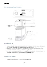
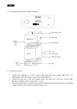
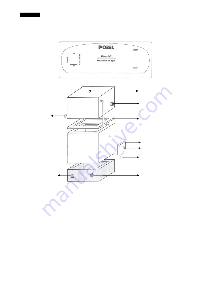
1.3.1. WATER DISTILLER. FRONT PANEL
1.4. INSTALLATION
1.
Connect the equipment to a 230 V power outlet using the power supply cable (110 V for
10DESA1041 and a three-phase connection for 10DESA0120)
2.
Connect the gray hose to the water supply socket. The other end of the hose, with the filter
previously installed, will be connected to a ¾ ”tap.
3.
The silicone tube must be connected to the outlet for distilled water and the other end to a collecting
container whose level is below the outlet by about 25 cm.
Refrigerante
Boiler
Steam exhaust hole
Water inlet
Silicone gasket
Level
Water drain valve
Reset
Distilled
water
outlet
ON/OFF
switch
Level switch
DESA 0_ _ _
Summary of Contents for DESA 0041
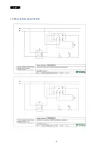
Page 7: ...ESP 6 1 9 DIAGRAMA ELECTRICO ...
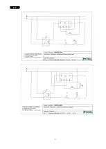
Page 8: ...ESP 7 ...
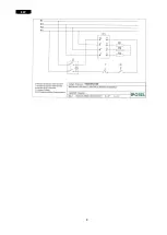
Page 9: ...ESP 8 ...
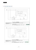
Page 15: ...ENG 14 1 9 ELECTRIC DIAGRAM ...
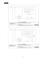
Page 16: ...ENG 15 ...
Page 17: ...ENG 16 ...


