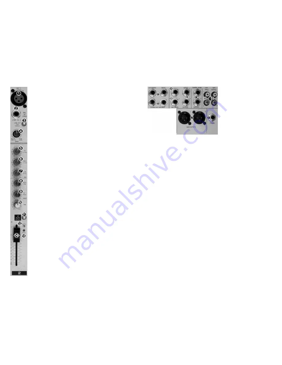
MONO MIC / LINE INPUT CONNECTIONS AND CONTROLS
①
MIC INPUTS (1 - 4)
Balanced XLR microphone input jack.
PIN 1: ground, PIN 2: (+) signal, PIN 3: (-) signal
P48VDC supply: PINS 2 and 3 (when activated)
Ribbon, condenser and dynamic microphones are accommodated.
②
LINE INPUTS (1 - 4)
Balanced ¼” phone jack (TRS). Line level input
TIP: (+) signal, RING: (-) signal, SLEEVE: ground
Any line level source (balanced or unbalanced) can be inserted here.
③
LOW CUT PUSHBUTTON
When on, reduces low frequency sounds such as air conditioning, traffic and MIC
stand vibrations. Specifications: -3dB @ 75Hz, 18dB/octave rolloff.
④
GAIN
Rotary MICrophone or LINE input sensitivity control. Use to set the level of this
channel relative to other inputs. Thus creating the desired “mix”. Do not use as a
fader.
⑤
HI EQ
Adjusts high frequencies up or down. Set to 0 (center detent) for no EQ.
⑥
MID EQ
Adjusts mid frequencies up or down. Set to 0 (center detent) for no EQ.
⑦
LOW EQ
Adjusts low frequencies up or down. Set to 0 (center detent) for no EQ.
⑧
MON
PRE
Adjusts the signal level sent to the AUX 1
bus.
“MON
PRE
” is before, or pre
FADER. This means FADER adjustments
will not
change the signal level being
sent to the AUX 1 bus.
⑨
FX
POST
FX is shorthand for Effects (reverb, echo, EQ). If you wish to route the signal
through an external device (effect) you would normally route it to the AUX 2 bus.
This control adjusts the signal level sent to the AUX 2 bus.
“FX
POST
” is after, or
post FADER. This means FADER adjustments
will
change the signal level being
sent to
the AUX 2 bus, allowing the level of the external effect to “follow” the
FADER.
⑩
PAN
Adjusts the relative
position of the sound across the “stage” (left/center/right).
⑪
MUTE
ALT
3/4
PUSHBUTTON
The channel output normally goes to the LEFT/RIGHT bus. When
“MUTE
ALT
3/4
“
is depressed the signal is re-directed to the ALT 3 & 4 bus, which has the effect of
muting the main output and making it available for headphone monitoring.
⑫
MUTE
LED
This yellow LED lights whenever the MUTE
ALT
3/4
⑪
is depressed.
⑬
PEAK
LED
This red LED lights when the input signal is too high. Lower input GAIN
④
or
source level when this occurs.
⑭
FADER
Use only to
“fade” the channel in or out during the performance. This is not a volume control.
4
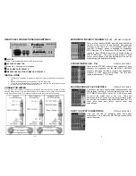
INPUT / OUTPUT CONNECTIONS
Ⓐ
AUX 1 SEND
Unbalanced
¼” phone jack, Tip
Sleeve (TS). The sum of all signals
sent to the AUX 1 bus are output
here. NOTE: All feeds to the AUX 1
bus are pre-fader, also known as
“dry”.
Ⓑ
AUX 2 SEND
Unbalanced ¼” phone jack (TS).
The sum of all signals sent to the
AUX 2 bus are output here. NOTE:
All feeds to the AUX 2 bus are post-
fader, also known as “wet”.
Ⓒ
STEREO AUX 1 RETURN
Balanced
¼” phone jack (TRS). The STEREO AUX 1 RETURN is sent to the
LEFT/RIGHT bus. If only the LEFT input jack is used the signal is sent to both the LEFT
and RIGHT channels. (MONO)
Ⓓ
STEREO AUX 2 RETURN
Balanced
¼” phone jack (TRS). The STEREO AUX 2 RETURN can be sent to either the
LEFT/RIGHT bus
or
the ALT 3
– 4 bus. If only the LEFT input jack is used the signal is
sent to both the LEFT and RIGHT (MONO).
Ⓔ
ALT 3
– 4 OUTPUTS
Unbalanced ¼” phone jack (TS). All signals sent to the ALT 3 – 4 bus (with the MUTE
switches) are combined and sent to these output connectors.
Ⓕ
CONTROL ROOM OUTPUTS L
and R
Unbalanced ¼” phone jack (TS). Normally used to provide line level signal to the
monitor speakers in the control room.
Ⓖ
TAPE INPUT
Unbalanced phono jacks (RCA). Normally used for a 2-track recording device input.
“TAPE INPUT” can also be used as an additional stereo line level input. For example,
additional sound elements can be added to the mix from a CD player, iPod, MP3 player
or computer.
Ⓗ
TAPE OUTPUT
Unbalanced phono jacks (RCA). Wired in parallel with the MAIN OUTPUTS
Ⓙ
.
Normally connected to the inputs of a 2-track recording device.
Ⓘ
PHONES
Unbalanced
¼” phone jack (stereo TRS). You can connect monitoring headphones
here. This output is the same signal as the CONTROL ROOM
Ⓕ
output.
Ⓙ
MAIN OUTPUTS
Balanced XLR jacks. The
LEFT and RIGHT “MAIN MIX” signals are available here.
9


