background image

26


EN


OPERATING INSTRUCTIONS

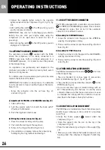
• Connect  the  cigarette  lighter  cable  to  the  cigarette 

lighter socket and to the compressor (fig . C1, fig . C2, fig . 

C3)

• After setting the switch 

2

 to the ON position, you can 

use the compressor directly .

IMPORTANT:  take  care  not  to  discharge  your  vehicle’s 

battery .  You  can  start  your  engine  when  using  the 

compressor  (in  an  open  area  to  avoid  the  risk  of 

poisoning) . 
• After turning the switch 

2

 to the OFF position, you can 

unplug your compressor .

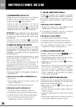
10. AUTOMATIC ANGLED CONNECTOR

The  automatic  connector 

11b  

,  supplied  with  the  R180, 

allows  the  compressor  to  be  easily  connected  to  a 

PRESTA  type  valve  (with  or  without  extension)  or  a 

SCHRADER type valve .  It is located in one of the pockets 

of the transport bag .

Its  ergonomics  are  particularly  well  adapted  to  the 

lenticular solid wheels . It holds in place by itself, even if 

there is a lot of pressure .

For a better ease of use we advise you to place the valve 

towards the bottom of the wheel .

IMPORTANT: this nozzle is a new process . It is advisable 

to carry out tests to have an optimum grip of the device . 

Never force .

-  Screw  the  connector  onto  the  air  hose  (fig .  J1)  

     and lock it (fig . J2) .

a) Adjustment for PRESTA or SCHRADER valve (fig. J3)

1 .  Take out the ring
2 .  Turn  the  selector  switch  to  match  the  mark  with  P 

(Presta) or S (Schrader) .

3 .  Push the ring back in before use

b) Fitting the inflation connector (fig. J4)

1 .  Press the connector firmly onto the valve
2 .  Then slide the red ring all the way down
3 .  Screw on the ring, without forcing, to lock
4 .  Once inflation is complete, remove the connector by 

holding it by the ring, without unscrewing it .

11. USE OF THE SCREW CONNECTOR

The R180 is equipped with a reversible screw connector 

11

 for PRESTA or SCHRADER type valves . This connector 

is  intended  for  valves  that  do  not  fit  the  automatic 

connector or are difficult to access . 

b) Assembly for SCHRADER valves

1 .  Screw the connector onto the pipe on the «PRESTA» 

side (fig . I1) and tighten it firmly .

2 .  Then screw the connector onto the valve (Fig . I2) until it 

locks (Fig . I3) . 

b) Assembly for PRESTA valves

1 .  Screw the connector onto the pipe on the «SCHRADER» 

side (fig . I4) and lock it firmly .

2 .  Then screw the connector onto the valve (Fig . I5) until it 

locks (Fig . I6) .

12. OTHER INFLATION ACCESSORIES

The R180 is delivered with 3 nozzle  

12


13


14   

 which are 

in the transport bag
• They  are  intended  for  various  types  of  accessories, 

balls or inflatable toys (fig . J1, fig . J2, fig . J3) .
• These nozzle are screwed onto the connector 

11

 on the 

PRESTA side (fig . J4)

• You can screw other types of inflation fittings with an 

M  11  thread  directly  onto  the  hose  or  onto  the  screw 

connector . Make sure that these accessories are used 

as intended and comply with the conditions of use as 

described in the chapter «Safety instructions» . 

13. USING THE CLIP-ON BIKE MOUNT

The R180 has a retractable bike mount that allows you to 

transform your compressor into a stand for a road bike 

(up to 9 kg)
• Unclip  the  metal  support 

10

  located  under  the 

compressor (fig . J1)

•  Slide  the  support  into  the  slot  on  the  top  of  the 

compressor (fig . J2)

• Place the rear wheel of your bicycle on the support (fig . 

J3)

• After use, you can remove the holder and place it in its 

housing under the compressor (magnetic holder) (fig . 

K4) .

Summary of Contents for 900180

Page 1: ...resseur Haute Pression avec batterie 12 V FR 9 High Pressure compressor with 12 V battery EN 19 Compresor de alta presi n con bater a de 12 V ES 29 Notice originale Original instructions Instrucciones...

Page 2: ...6 7 10 11 9b 9 16 17 20 19 18 15 2 3 4 5 8 12 13 14 1 2 11b a...

Page 3: ...27 28 29 30 4 3 33 31 32 2 26 25 24 23 22 21 3 c b...

Page 4: ...2 2 A1 D1 A2 D2 B1 C1 C2 C3 16 15 100 240 V 50 60 Hz 2 20 20 20 2 2 50 100 0 50 4 12 V 20 A DC B2 C4...

Page 5: ...E1 G1 G2 G3 F1 F2 E3 F3 STOP 3 s E2 24 25 5...

Page 6: ...H1 H3 H4 H2 Schrader Presta 1 1 3 2 2 3 4 34 35 36 M11x0 8 6...

Page 7: ...DER VALVE SCHRADER VALVE SCHRADER VALVE PRESTA VALVE PRESTA VALVE PRESTA VALVE I4 I6 I5 11 11 11 11 11 11 P r e s t a Sch r a d e r P r e s t a Sch r a d e r Pr e s t a S c h r a d e r Pr e s t a S c...

Page 8: ...K1 K4 K2 10 10 8 K3 Pr e s t a S c h r a d e r J4 11 10 10 12 13 14 J1 J2 J3...

Page 9: ...ion charger compl tement la batterie une charge compl te dure 8 heures 2 Pour charger l appareil placer l interrupteur principal sur ON 3 Recharger le compresseur apr s toute utilisation et au moins t...

Page 10: ...utilisation des fins professionnelles et frais de port et d emballage retour de l appareil ces derniers restent la charge du client Tout article envoy en r paration en port d sera refus La garantie se...

Page 11: ...se pour gonflage ballon 15 Fiche du chargeur 100 240 V AC 12 V DC 16 Chargeur 100 240 V AC 12 V DC 17 Adaptateur pour prise electrique norme GB 18 Fiche du C ble allume cigare 12V 19 C ble 12 V 3 m 20...

Page 12: ...amais de r parer vous m me le produit Ne faites r parer ou remplacer les pi ces endommag es ou d fectueuses que par un personnel autoris N ouvrez pas le produit vous m me Manipulez le produit avec pr...

Page 13: ...guli rement la temp rature de l appareil Interrompez imm diatement le processus de chargement en cas de forte surchauffe Une batterie qui chauffe fortement ou se d forme au cours du chargement est d...

Page 14: ...de transport avec poches int rieures 2 LES UTILISATIONS POSSIBLES V LO DE ROUTE gonflage des pneus gonflage des boyaux gonflage des tubeless VTT gonflage des pneus gonflage des tubeless gonflage des a...

Page 15: ...de fonctionnement ou pour le charger mettre l interrupteur g n ral 2 sur ON La led verte 31 s allume fig A2 Si la batterie est charg e moins de 50 c est la led orange 32 qui s allume L cran tableau de...

Page 16: ...rmement le connecteur sur la valve 2 Puis faire coulisser la bague rouge fond 3 Visser la bague sans forcer pour verrouiller 4 Une fois le gonflage termin retirer le connecteur en le tenant par la bag...

Page 17: ...0 14 EC modifi e par 2005 88 EC IEC61056 1 2014 35 EU 2011 65 EU 2015 863 annexe 2 et valu selon les normes applicables en vigueur suivantes EN 1012 1 2020 EN 60204 1 2018 EN 55014 2017 EN 55014 2 201...

Page 18: ...passez en mode 12 V en branchant le compresseur sur la prise 12 V DC de l allume cigare Fuite d air V rifiez le tuyau le faire changer si n cessaire Mauvaise connexion du connecteur Resserrer ou rempl...

Page 19: ...the first time fully charge the battery a full charge lasts 8 hours 2 2 To charge the unit turn the main switch to ON 3 Recharge the compressor after every use and at least every 3 months using the 10...

Page 20: ...nal purposes and postage and return packaging costs for the device these remain the responsibility of the customer Any item sent for postage repair will be refused The warranty will be automatically c...

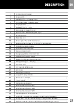
Page 21: ...on nozzle 15 Charger plug 100 240 V AC 12 V DC 16 100 240 V AC 12 V DC charger 17 Adapter for GB standard electrical outlet 18 12V cigarette lighter cable plug 19 12 V cable 3 m 20 12 V cigarette ligh...

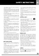
Page 22: ...ce unattended during use Always stay with the compressor during the process and monitor the inflation status When the inflatable item approaches its maximum inflation threshold it is important that yo...

Page 23: ...le charging and check the temperature of the device regularly Interrupt the charging process immediately in the event of severe overheating A battery that heats up strongly or deforms during charging...

Page 24: ...tion of tubulars tubeless inflation MTB GRAVEL tire inflation tubeless inflation inflation of shock absorbers and forks AUTOS MOTORCYCLES and other VEHICLES tire inflation subject to control by CE mea...

Page 25: ...ery is charged at less than 50 the orange LED 32 q lights up The control panel screen then 1 lights up and the compressor makes a reset all the LEDs 21 light up After a few seconds the screen stabiliz...

Page 26: ...Once inflation is complete remove the connector by holding it by the ring without unscrewing it 11 USE OF THE SCREW CONNECTOR The R180 is equipped with a reversible screw connector 11 for PRESTA or S...

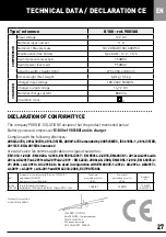
Page 27: ...d by 2005 88 EC IEC61056 1 2014 35 EU 2011 65 EU 2015 863 annexe 2 et valu selon les normes applicables en vigueur suivantes EN 1012 1 2020 EN 60204 1 2018 EN 55014 2017 EN 55014 2 2015 EN60335 1 2012...

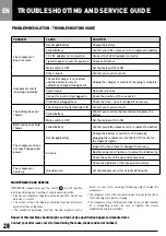
Page 28: ...ttery or switch to 12 V mode by plugging the compressor into the 12 V DC socket on the cigarette lighter Air leak Inspect the hose Have it changed if necessary Bad tip connection Tighten or replace th...

Page 29: ...cargue completamente la bater a una carga completa dura 8 horas 2 Para cargar la unidad ponga el interruptor principal en ON 3 Recargue el compresor despu s de cada uso y al menos cada 3 meses utiliza...

Page 30: ...uso con fines profesionales y los gastos de env o de vuelta del aparato estos ltimos siguen siendo responsabilidad del cliente Cualquier art culo enviado para su reparaci n con los gastos de env o ve...

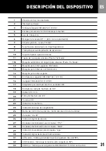
Page 31: ...h n de aire 14 Boquilla para inflar el globo 15 Enchufe del cargador 100 240 V AC 12 V DC 16 Cargador 100 240 V AC 12 V DC 17 Adaptador para enchufe el ctrico est ndar GB 18 Enchufe de cable de mecher...

Page 32: ...producto usted mismo Manipule el producto con cuidado Un golpe una sacudida o una ca da incluso desde poca altura puede da ar el producto Si el cable de alimentaci n de CA del cargador est da ado deb...

Page 33: ...ho o se deforma durante la carga es defectuosa No siga utilizando la bater a No exponga la bater a incorporada a esfuerzos mec nicos No deje caer golpee doble o corte la bater a Nunca descargue comple...

Page 34: ...los interiores 2 POSIBLES USOS CICLISMO DE CARRETERA inflado de neum ticos inflado de mangueras inflar el tubeless CICLISMO DE MONTA A inflado de neum ticos inflar el tubeless inflado de amortiguadore...

Page 35: ...agados fig A1 Para poner el compresor en funcionamiento o para cargarlo ponga el interruptor principal 2 en ON El LED verde 31 se encender fig A2 Si la bater a est cargada a menos del 50 el LED naranj...

Page 36: ...3 Atornille el anillo sin hacer fuerza para bloquearlo 4 Una vez terminado el inflado retire el conector sujet ndolo por el anillo sin desenroscarlo 11 USO DEL CONECTOR DE TORNILLO El R180 est equipad...

Page 37: ...EC modifi e par 2005 88 EC IEC61056 1 2014 35 EU 2011 65 EU 2015 863 annexe 2 y evaluado de acuerdo con las siguientes normas aplicables en vigor EN 1012 1 2020 EN 60204 1 2018 EN 55014 2017 EN 55014...

Page 38: ...ie al modo de 12 V conectan do el compresor a la toma de 12 V DC del encendedor Fuga de aire Compruebe la manguera y h gala cambiar si es necesario Mala conexi n del conector Apriete o sustituya el co...

Page 39: ...39 39...
Page 40: ...900180 POGGIO SOLUTIONS COM Import par Imported by POGGIO SOLUTIONS 854 avenue du campon 06110 LE CANNET FRANCE...

Reviews: