© Copyright Poindus Systems 2012 P21 / 54
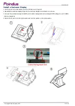
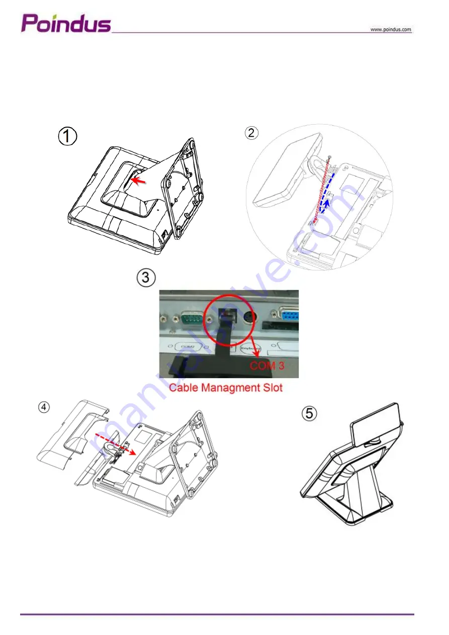
Install a Customer Display
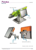
1. Put the panel on the flat table & open the IO back cover of system.
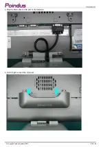
2. Assemble the customer display hinge into the customer display slot and fasten 2 x screws.
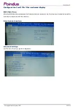
3. Connect the customer display into COM3 via the cable management slot and adjust COM3 voltage to +12V in BIOS
(refer to Chapter 6)
4. Fasten the IO cover into the right position and turn the system on the right position.
Summary of Contents for VariPOS 815
Page 1: ...Copyright Poindus Systems 2012 P1 54 User Manual Version V2 1 Dec 2012 VariPOS 815...
Page 5: ...Copyright Poindus Systems 2012 P5 54...
Page 6: ...Copyright Poindus Systems 2012 P6 54...
Page 18: ...Copyright Poindus Systems 2012 P18 54...
Page 26: ...Copyright Poindus Systems 2012 P26 54 5 Done...
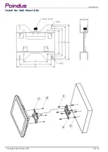
Page 34: ...Copyright Poindus Systems 2012 P34 54 Install the Wall Mount Kits...
Page 35: ...Copyright Poindus Systems 2012 P35 54 Motherboard information Motherboard Layout Sandy Bridge...


