background image


STT11-65E 

 wireless operation 

User manual 

8/22 

IV. General description of assembly  

Follow the manual below to assemble the stand set. The product is delivered in parts. One complete set contains two 
bases, two posts, two crossbar supports, CPU (central processing unit),  PTC (portable tablet computer). To assemble 
the stand set you will need: 

- hex key 6 and 8 
- flat wrench no. 13 
- flat wrench no. 19 
- flat wrench no. 30. 

We  recommend  that  the  assembly  process  would  take  place  at  the  target  location  because  it  is  easier  to  move 
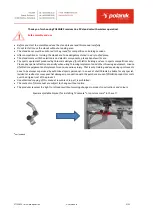
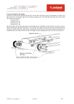
separate stand parts than the whole structure. The trolleys in the bases are secured from uncontrolled movements 
by means of special safety bars while the set is transported. The safety bar should remain fastened until the post is 
screwed down to the trolley of the base. After that stage has been completed you have to remove the safety bars.  


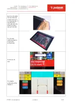
safety bar screws

safety bar immobilizes 

the trolley

holes to fasten the base to the ground

Summary of Contents for STT11-65E

Page 1: ...USER MANUAL Competition pole vault electric stand set wireless operation STT11 65E File 2019 05 22 PRODUCT SUPPORT Pawel Ciechanowski p ciechanowski polanik com ...

Page 2: ...ts competitions only Please pay special attention especially when using throwing implements and other throwing equipment misuse of athletics equipment and implements can cause serious injury That is why training and use during sports events have to be always supervised by authorized sports personnel In no event shall Polanik be liable for any special incidental indirect or consequential damages in...

Page 3: ...ion Our electrical version of the competition PV stand completes fully the product offer Each stand is driven by two step motors The operator uses a portable tablet computer PTC to operate wirelessly the PV stands Entered values are processed by the main unit CPU which drives the step motors The tablet PTC lets you position the crossbar in more comfortable quicker and more precise way than in ordi...

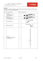
Page 4: ...or athletics competitions of pole vaulting The set includes the following elements Item no Part set description Q ty Pcs Part set sketch 1 Left base screw M 20x40 4 pcs washer 20 4 pcs 1 2 Right base screw M 20x40 4 pcs washer 20 4 pcs 1 3 Left crossbar support 1 4 Right crossbar support 1 5 Left post countersunk hex key screw M 10x40 4 pcs 1 ...

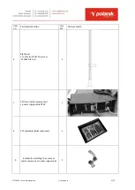
Page 5: ...et description Q ty Pcs Part set sketch 6 Right post countersunk hex key screw M 10x40 4 pcs 1 7 CPU central processing unit power supply cable 230V 1 8 PTC portable tablet computer 1 9 Bracket for installing TV camera or sports camera on crossbar support arm 1 ...

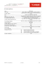
Page 6: ...ware for the official operator Crossbar support lifting mechanism step motor super smooth operation system based on ball bearings Post shifting mechanism step motor supper smooth operation system based on special guide rolls Height range cm 210 628 Crossbar support horizontal shift cm 0 15 Post horizontal shift range cm 0 80 Crossbar bias correction range mm 0 80 Power supply European version 230V...

Page 7: ...STT11 65E wireless operation User manual 7 22 STT11 65E dimensions mm ...

Page 8: ...wrench no 19 flat wrench no 30 We recommend that the assembly process would take place at the target location because it is easier to move separate stand parts than the whole structure The trolleys in the bases are secured from uncontrolled movements by means of special safety bars while the set is transported The safety bar should remain fastened until the post is screwed down to the trolley of t...

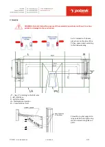
Page 9: ...ction As it is marked on the bases place them on the sides of the PV box spaced apart according to the below drawing 0 line 0 according to the IAAF rules L left stand base R right stand base LA landing area projection PV Pole Vault box mm Screw the crossbar supports to lying posts left and right using screws screwed into guides on posts crossbar support mounting holes in the runner ...

Page 10: ...bels Unscrew the screws M20x40 4 pcs marked S they will be needed to fasten the post After that the post is ready to be installed on the base trolley Press hinge pin levers according to the arrows Place hinge pin levers between catches Position stand post foot over the hinge hinge pin ...

Page 11: ...eir working positions and connect post foot with base trolley That pivotal joint is used to put posts in the upright position Lift the post to vertical position Then one person holds the post and the second one screws S unscrewed before M20x40 screws 4 pcs with washers 20 4 pcs Screw the screw which is on the opposite side of post s hinge first ...

Page 12: ... of that operation may cause stands overturn and result in serious accident or damages It is recommended that the bases are fastened to the ground with hex nut head steel sleeve anchors dia 16 mm and length 140 mm holes must be of dia 16 mm and 130 150 mm deep The concrete base is to be dry and non cracked For the installation of the anchors please see their producer s instruction The stands are r...

Page 13: ...ply is not on Before turning a power supply on you must connect all the set elements Connectors posts and bases are marked with numbers from 1 to 4 see below Place CPU near the left stand and connect all the connectors in the way the diagram shows below No 1 to crossbar supporter s motor left stand No 2 to base s motor left stand No 3 to crossbar supporter s motor right stand No 4 to base s motor ...

Page 14: ...er the landing area platform and landing area make sure not to crush them The cable to the post motor should be placed outside It needs free room to move within the range 0 80 cm towards the landing area Connect CPU with the power supply using the included cable and switch on the power ...

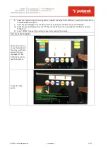
Page 15: ...e tablet Press and hold the power button for 3 s and wait awhile If the tablet does start please see the tablet instruction manual for details The PV stand operating program should start automatically Tap the icon to start The program window should be displayed ...

Page 16: ...the entered position Touch the button It moves the crossbar to the entered position Touch the button It stops all the actions Touch the button if the wireless connection between the tablet and the uprights has not been automatically established starts the connection Touch the button It lets you lower the supports to place the crossbar Touch the button Operation step by step 1 Connect all the cable...

Page 17: ... field next to its description HEIGHT and press START 10 Enter the desired distance from the 0 line into the field next to its description LENGTH and press START 11 Press HOME to lower the crossbar supports for placing the crossbar How to use the help guide Move the screen up to see the bottom of the screen with help guides Tab your language PL EN RU DE ES or FR to see the help text Follow the hel...

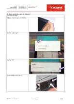
Page 18: ...65E wireless operation User manual 18 22 VII How to switch off properly the PV stands Switch off the tablet Press and hold the power button for 3 s Confirm switching off Confirm OK Switch off the power in CPU ...

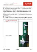
Page 19: ...nd stored in a dry roofed room with minimal temperature of 5 C and maximal humidity of 80 The base wheels should be only used to transport stands on level surfaces and within short distances You should unscrew the posts from the bases and secure the base trolleys with safety bars to transport the stands for long distances IX Emergency manual backup In case of emergency power loss failure or damage...

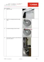
Page 20: ...manual 20 22 Step Description Illustration 3 Take off the crank 4 Take off the mounting plate with the blocking screw 5 Unscrew the blocking screw from the plate 6 Use the crank to unscrew the washer of the stand axle counter clockwise ...

Page 21: ... the crank to screw it down to the stand axle 9 Install the blocking screw A To install the crank B put in the still pegs at the angle first and push it down 10 Adjust the desired height and then remove the crank Turn the blocking crew to immobilize the crossbar support 11 Use the backup measuring scale on the post to position the crossbar supports ...

Page 22: ...STT11 65E wireless operation User manual 22 22 X IAAF certificate ...

Reviews: