EVCO S.p.A.
Vcolor 869
| Installer manual ver. 1.0 | Code 144VC869E104
page 11 of 92
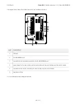
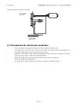
The diagram below shows the intended use of the user interface connectors.
PART
DESCRIPTION
1
USB port
2
RS-485 MODBUS port
3
dip switch for the termination resistor for the RS-485 MODBUS port
4
power supply for the user interface and connection between the user interface and the control module
5
dip switch for the resistor connecting the user interface and the control module
6
appliance earthing
For more information see subsequent sections.


