EVCO S.p.A.
Vcolor 869
| Installer manual ver. 1.0 | Code 144VC869E104
page 12 of 92
2.2
Control module description
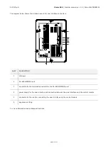
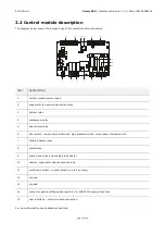
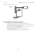
The diagram below shows the intended use of the control module connectors.
PART
DESCRIPTION
1
control module power supply
2
evaporator fan and condenser fan relay
3
defrost relay
4
compressor relay
5
door heater relay
6
door switch, low pressure switch and high pressure switch, compressor thermal switch
7
thawing heater relay
8
alarm relay
9
pump down relay and needle probe heater
10
cabinet, evaporator and condenser probe
11
multi-point probe or needle probes (up to 3 sensors)
12
unused
13
unused
14
output for phase cutting speed regulator for EVDFAN1 single-phase fans
15
user interface – control module connection
For more information see subsequent sections.


