8 FRONT WHEEL, FRONT BRAKE
,
SUSPENSION
,
STEERING
8-6
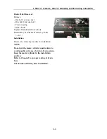
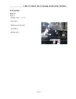
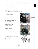
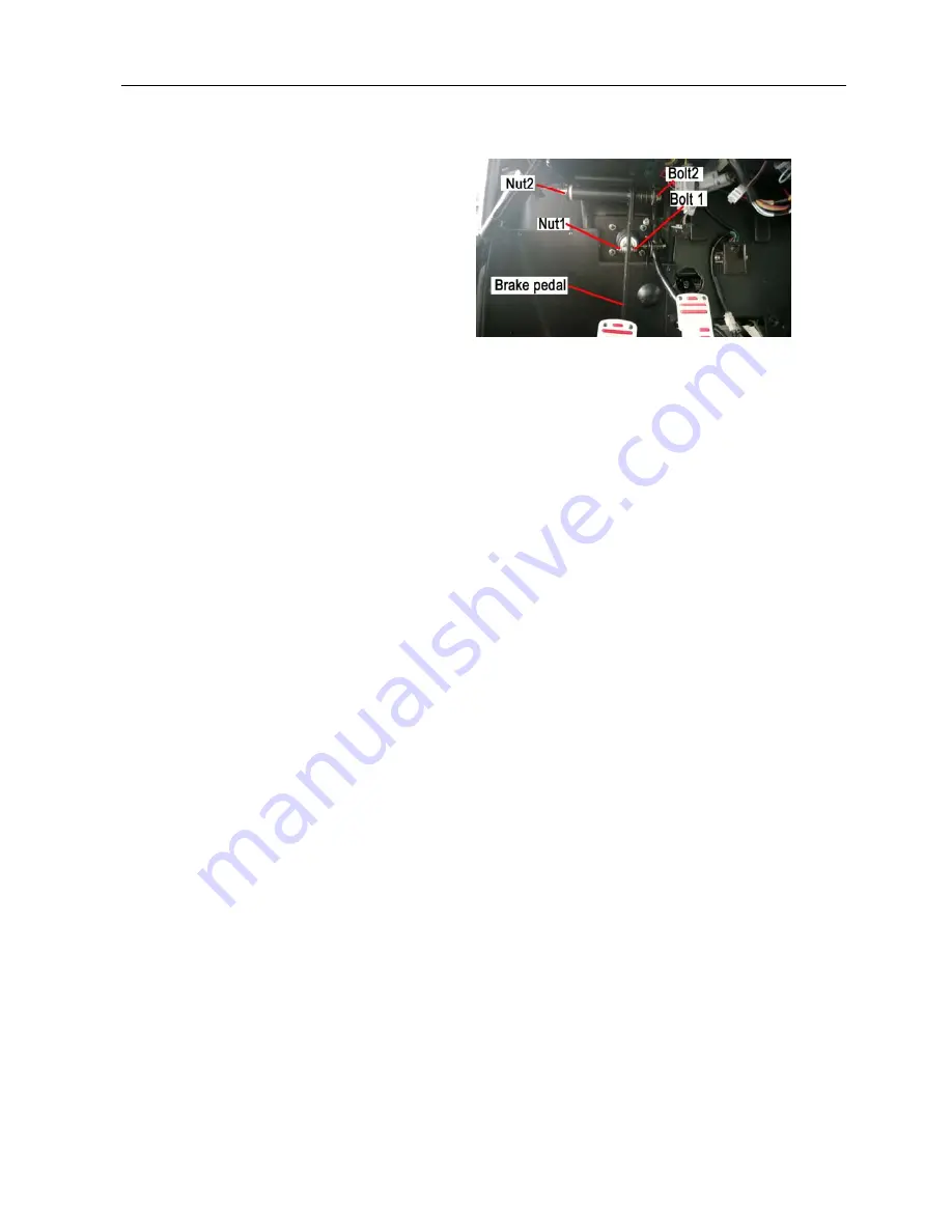
Brake Pedal Removal
Remove:
--One bolt 1 and one nut 1
-- One bolt 2 and one nut 2
-- Torsion spring
--
Brake Pedal
Seperate Brake Pedal from vehicle
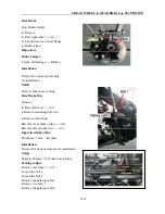
Disassembly of front brake master cylinder
(
→
8-5
)
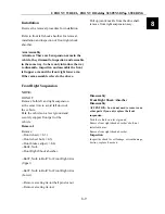
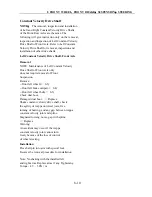
Installation
Reverse the removal procedure for installation.
NOTE
Do not put the master cylinder upside down to
avoid possible entrance of air into brake system.
Keep the master cylinder in the installation
position.
Refer to Chapter1 for proper routing of brake
hose.
Check brake efficiency after installation.
Summary of Contents for 1100 GKE OutLaw
Page 1: ...Service Manual 1100GKE 4 4...
Page 62: ...4 COOLING SYSTEM 4 6 Cooling System Chart...
Page 158: ...10 CVT TRANSMISSION SYSTEM 10 7 5 Appearance installation dimension map Fan shaped array 10...
Page 165: ...11 EFI SYSTEM OF SQR 472ENGINE 11 3 3 The ECU control principle diagram...
Page 166: ...11 EFI SYSTEM OF SQR 472ENGINE 11 4 4 The ECU function module layout...
Page 260: ......

