1. SERVICE INFORMATION
1-12
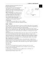
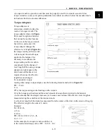
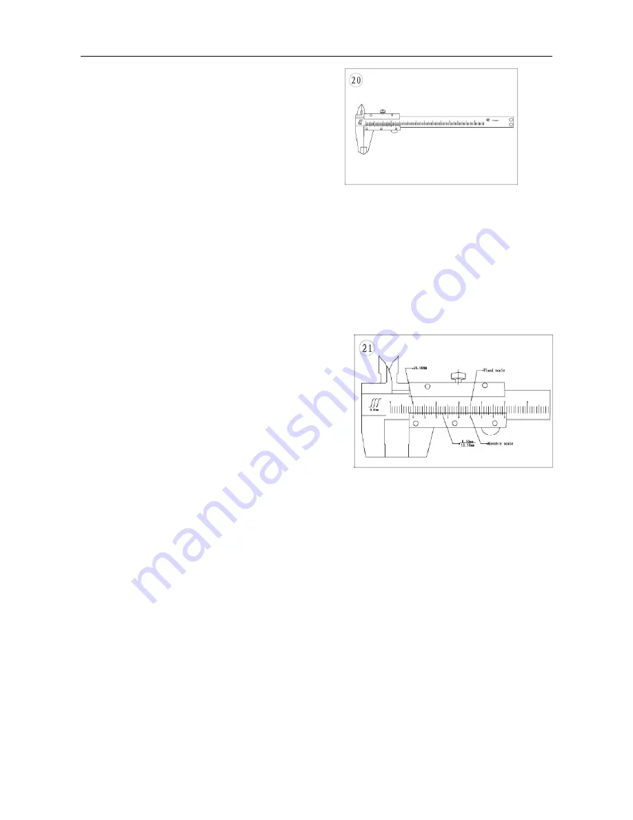
Calipers
Calipers (
Figure 20
) are excellent tools for
obtaining inside, outside and depth measurements.
Although not as precise as a micrometer, they allow
reasonable precision, typically to within 0.05 mm
(0.001 in.). Most calipers have a range up to 150 mm
(6 in.).
Calipers are available in dial, venire or digital versions. Dial calipers have a dial readout that
provides convenient reading. Venire calipers have marked scales that must be compared to
determine
the measurement. The digital caliper uses a liquid-crystal display (LCD) to show the measurement.
Properly maintain the measuring surfaces of the caliper. There must not be any dirt or burrs
between the tool and the object being measured. Never force the caliper to close around an object.
Close the caliper around the highest point so it can be removed with a slight drag. Some calipers
require calibration. Always refer to the manufacturer’s instructions when using a new or unfamiliar
caliper.
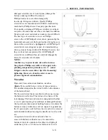
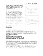
To read a vernire. Calipers refer to
Figure 21
. The
fixed scale is marked in l-mm increments. Ten
individual lines on the fixed scale equal 1 cm. The
movable scale is marked in 0.05 mm (hundredth)
increments. To obtain a reading, establish the first
number by the location of the 0 line on the movable
scale in relation to the first line to the left on the fixed
scale. In this example, the number is 10 mm. To
determine the next number, note which of the lines on
the movable scale align with a mark on the fixed scale.
A number of lines will seem close, but only one will align exactly. In this case, 0.50 mm is the
reading to
add to the first number. Adding 10 mm and 0.50 mm equals a measurement of 10.50 mm.
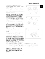
Micrometers
A micrometer is an instrument designed for linear measurement using the decimal divisions of
the inch or meter (
Figure 22
). While there are many types and styles of micrometers, most of the
Summary of Contents for 1100 GKE OutLaw
Page 1: ...Service Manual 1100GKE 4 4...
Page 62: ...4 COOLING SYSTEM 4 6 Cooling System Chart...
Page 158: ...10 CVT TRANSMISSION SYSTEM 10 7 5 Appearance installation dimension map Fan shaped array 10...
Page 165: ...11 EFI SYSTEM OF SQR 472ENGINE 11 3 3 The ECU control principle diagram...
Page 166: ...11 EFI SYSTEM OF SQR 472ENGINE 11 4 4 The ECU function module layout...
Page 260: ......


