8 FRONT WHEEL, FRONT BRAKE
,
SUSPENSION
,
STEERING
8-9
Installation
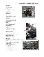
Reverse the removal procedure for installation.
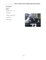
Refer to front left shock absorber for removal,
installation and inspection of front right shock
absorber.
Arm Assembly
Attention: There are 8 suspension arms in the
vehicle, they dismantle, inspection and assemble
in the same way. So here only introduce the way
to dismantle, inspection and assemble the front
left upper arm and the front right lower arm.
Other arm assemble refers to the above.
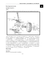
Front Right Suspension
NOTE:
DO NOT
Remove both left and right suspension
at the same time to avoid fall down of
the vehicle.
Park the vehicle on a level ground and
securely support front part of the
vehicle.
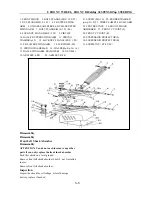
Removal:
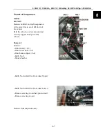
Remove:
--Front wheel(
→
8-3)
--Front wheel hub(
→
8-3)
--Front brake caliper(
→
8-4)
--Bolt2, Nut3.
--Front Right Shock absorber.
--Bolt7, Nut8 to Bolt7 for Front Right Arm
(Upper)
--Bolt7, Nut8 to Bolt7 for Front Right Arm
(Lower)
--
Remove steering tie-rod ball pin slot nut
--
Remove steering tie-rod.
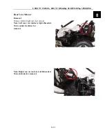
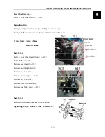
Pull up joint knuckle from the driveshaft,
remove front right suspension assy.
Disassembly
Front Right Shock Absorber
Disassembly
ATTENTION: You do not need to remove any
other parts if you only replace the front
suspension.
Park the vehicle on a level ground,
Remove front right shock absorber’s bolt, nut
installed in arm.
Remove front right shock absorber.
Inspection
Inspect the shock for oil leakage, oil seal damage,
destroy, replace if needed.
8
Summary of Contents for 1100 GKE OutLaw
Page 1: ...Service Manual 1100GKE 4 4...
Page 62: ...4 COOLING SYSTEM 4 6 Cooling System Chart...
Page 158: ...10 CVT TRANSMISSION SYSTEM 10 7 5 Appearance installation dimension map Fan shaped array 10...
Page 165: ...11 EFI SYSTEM OF SQR 472ENGINE 11 3 3 The ECU control principle diagram...
Page 166: ...11 EFI SYSTEM OF SQR 472ENGINE 11 4 4 The ECU function module layout...
Page 260: ......

