11. EFI SYSTEM OF SQR 472ENGINE
11-40
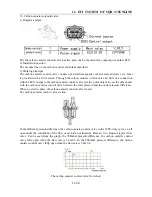
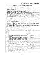
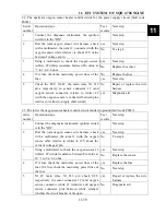
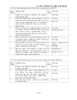
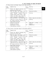
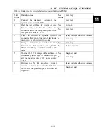
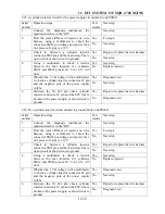
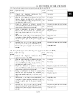
2.4. The lower oxygen sensor heater control circuit for the power supply circuit (fault code P0038)
Serial
number
Operation steps
Test
results
Next step
1
Connect the diagnostic instrument, ignition switch is
in the "ON"
Next
step
Yes Next
step
2
Dial the joint oxygen sensor wire harness, check
with a multimeter, the joint 1# (and oxygen sensor
connector, white 2# (relative) and oxygen sensor
connector relative to white) is 12V about the value
of voltage at pin.
No
To step 4
Yes Next
step
3
Using a multimeter to check the oxygen sensor 1#
(white), 2# (white) resistance between Pin value at
20
℃
in 5.4~6.6 ohm
No
The replacement of Xu
feelings
Yes Replace
the
fuse
4
15A fuse check the main relay power lines of the
fuse
No Next
step
Yes
Repair or replace the wire
harness
5
Check the ECU X1_9#, the main relay X1 -- 21#
pins respectively and sensor connector 1# (and
oxygen sensor connector, relative to white) 2#
(relative with the oxygen sensor cable) whether to
short circuit of power supply pin.
No Diagnostic
aid
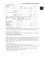
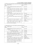
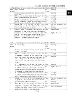
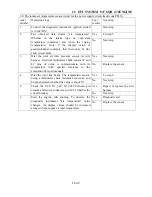
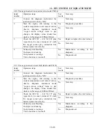
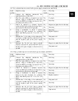
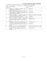
2.5. Manifold pressure sensor circuit shorted to ground (fault code P0107)
Serial
number
Operation steps
Test
results
Next step
1
Connect the diagnostic instrument, ignition switch is
in the "ON"
Next
step
Yes
To step 5
2
The observed data stream "pressure", is about
101kPa (numerical and Kia)
No Next
step
Yes
To step 5
3
Dial the joint air inlet pressure sensor on wire
harness, multimeter voltage check the joint 2# and
4# pins between whether the value is about 5V
No
Next step
Yes
Repair or replace the wire
harness
4
Check the ECU X1_60#, X1_46#, X1_48# pins
were in line between the sensor connector, 1#, 2#,
4# pin is broken
No Next
step
Yes Diagnostic
aid
5
Start the engine, idle running. Slow down on the
accelerator to close to the fully open, to observe the
diagnostic instrument "pressure" value changes, the
display values should change little; quick throttle to
close to the fully open, the display values should be
can instantly reach above 90kPa.
No Replace
the
sensor
Summary of Contents for 1100 GKE OutLaw
Page 1: ...Service Manual 1100GKE 4 4...
Page 62: ...4 COOLING SYSTEM 4 6 Cooling System Chart...
Page 158: ...10 CVT TRANSMISSION SYSTEM 10 7 5 Appearance installation dimension map Fan shaped array 10...
Page 165: ...11 EFI SYSTEM OF SQR 472ENGINE 11 3 3 The ECU control principle diagram...
Page 166: ...11 EFI SYSTEM OF SQR 472ENGINE 11 4 4 The ECU function module layout...
Page 260: ......

