5. REMOVAL OF ENGINE, TRANSMISSION SYSTEM AND GEARSHIFT
5-8
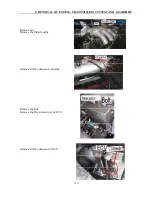
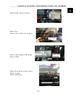
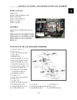
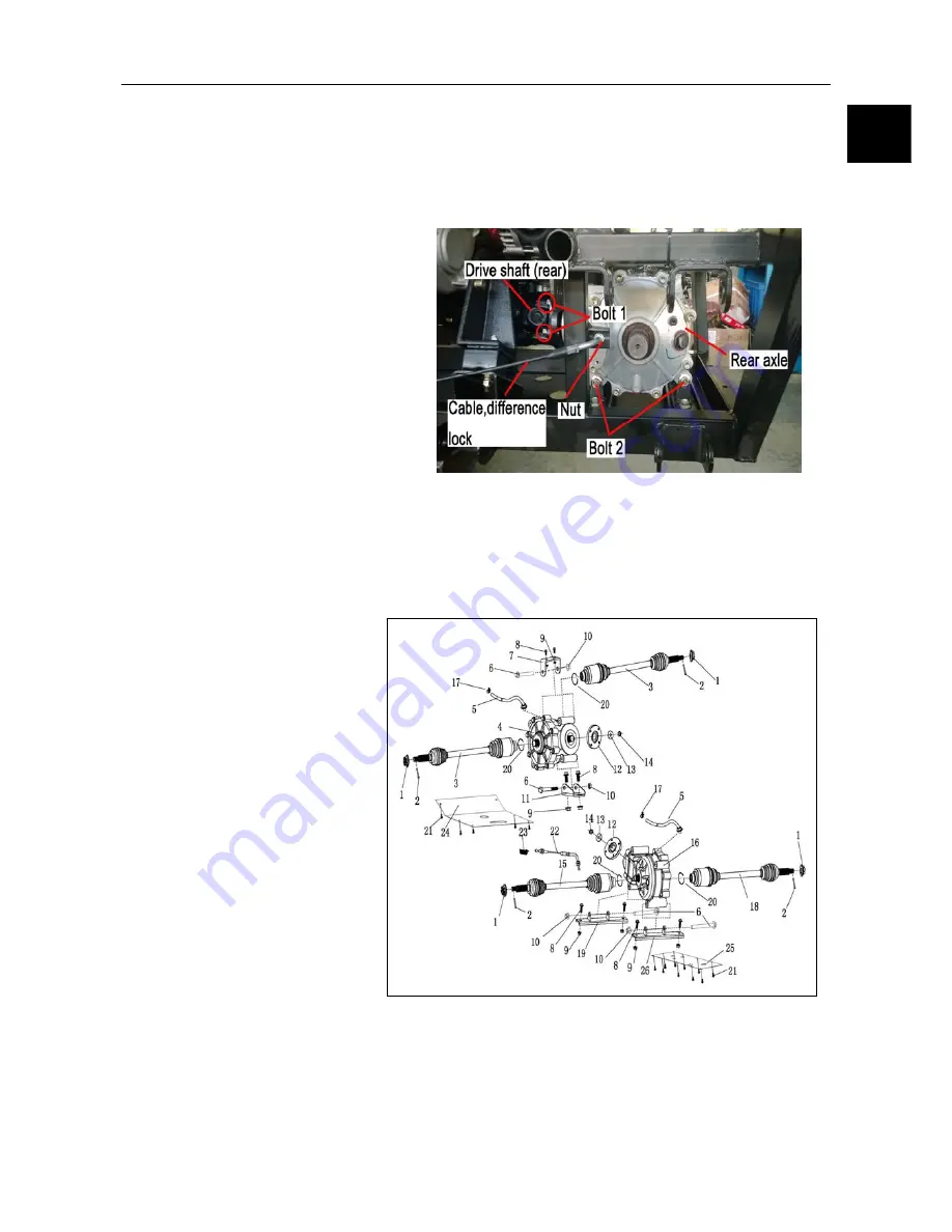
Remove rear axle.
Remove nut.
Remove Cable of difference lock.
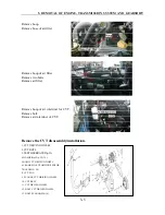
Remove four bolts 1.
Remove drive shaft (rear).
Remove two bolts 2.
Remove rear axle
Installation
Installation as contradictorily process of
remove
Bolt torque of rear axle (M8): 23-25N
·
m
Bolt torque of rear axle (M10): 45-50N
·
m
Bolt torque of rear drive shaft (M8):
23-25N· m
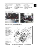
Front and rear axle assy disassembly/installation
1
.
NUT,SHAFT SET(M18×1.5)
2
.
PIN,SPLIT(4×30)
3. SHAFT SET,R.REAR(ATV904)
4. FRONT AXLE
5. AIR HOSE,AXLE
6. BOLT,FLANGE(M12×1.25×120)
7. DEAD PLATE,FRONT AXLE(F)
8. BOLT,FLANGE(M10×1.25×25)
9. LOCKNUT,FLANGE(M10×1.25)
10. LOCKNUT,FLANGE(M12×1.25)
11. DEAD PLATE,FRONT(R).
12. COUPLING FLANGE,FRONT
TRANSMISSION SHAFT
13. WASHER(
φ
16×
φ
30×2)
14. NUT(M14×1.5)
15. SHAFT SET,L.REAR(ATV905)
16. REAR AXLE
17. CLAMP(
φ
12
)
18. SHAFT SET,R.REAR(ATV912)
19. SUPPORT,FRONT AXLE 20. C-CIRCLIP 21. SCREW(M6×16)
22. CABLE,DIFFERENCE LOCK 23. EXTENSION SPRING,DIFFERENTIAL LOCK
24. GUARD,FRONT AXLE 25. GUARD,REAR AXLE 26. SUPPORT,REAR AXLE
5
Summary of Contents for 1100 GKE OutLaw
Page 1: ...Service Manual 1100GKE 4 4...
Page 62: ...4 COOLING SYSTEM 4 6 Cooling System Chart...
Page 158: ...10 CVT TRANSMISSION SYSTEM 10 7 5 Appearance installation dimension map Fan shaped array 10...
Page 165: ...11 EFI SYSTEM OF SQR 472ENGINE 11 3 3 The ECU control principle diagram...
Page 166: ...11 EFI SYSTEM OF SQR 472ENGINE 11 4 4 The ECU function module layout...
Page 260: ......

