Chery QQ Service Manual
Mechanical Part of SQR 472Engine
6-1
CONTENTS
Chapter 1 Reading Instruction ...................................................................................................................................... 2
1) Reading method of Maintenance Instruction............................................................................................................ 2
2) Meaning of Marks and Abbreviations ...................................................................................................................... 3
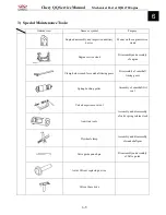
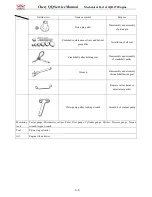
3) Special Maintenance Tool......................................................................................................................................... 4
Chapter 2 Disassembly, Assembly and Maintenance.................................................................................................... 6
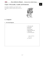
1) Timing Belt............................................................................................................................................................... 6
1. Structure Diagram............................................................................................................................................. 6
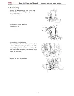
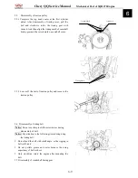
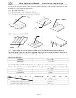
2. Disassembly ...................................................................................................................................................... 7
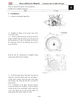
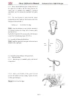
3. Installation ...................................................................................................................................................... 10
2) Camshaft................................................................................................................................................................. 13
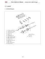
1. Structure Diagram........................................................................................................................................... 13
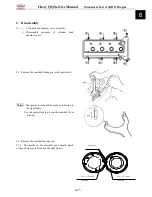
2. Disassembly .................................................................................................................................................... 14
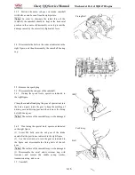
3. Installation ...................................................................................................................................................... 16
4. Routine Inspection of Valve ............................................................................................................................ 19
3) Cylinder Head......................................................................................................................................................... 22
1. Structure Diagram........................................................................................................................................... 22
2. Disassembly .................................................................................................................................................... 23
3. Routine Inspection .......................................................................................................................................... 23
4) Water Pump ............................................................................................................................................................ 29
1. Structure Diagram........................................................................................................................................... 29
2. Disassembly .................................................................................................................................................... 29
3. Cleanup ........................................................................................................................................................... 29
4. Routine Inspection .......................................................................................................................................... 29
5. Assembly......................................................................................................................................................... 29
5) Oil Pump................................................................................................................................................................. 29
1. Structure Diagram........................................................................................................................................... 30
2. Disassembly .................................................................................................................................................... 30
3. Cleanup ........................................................................................................................................................... 30
4. Disassembly and Assembly of Engine Oil Pump............................................................................................ 43
4.1 Structure Diagram................................................................................................................................. 42
4.2 Disassembly .......................................................................................................................................... 42
4.3 Routine Inspection ................................................................................................................................ 42
4.4 Installation............................................................................................................................................. 44
5. Disassembly of Oil Seal.................................................................................................................................. 45
5.1 Structure Diagram................................................................................................................................. 45
5.2 Disassembly .......................................................................................................................................... 46
5.3 Inspection.............................................................................................................................................. 46
5.4 Assembly of Oil Seal ............................................................................................................................ 46
6 Assembly.......................................................................................................................................................... 46
6) Crank Connecting Rod Mechanism........................................................................................................................ 46
1. Structure Diagram........................................................................................................................................... 48
2. Disassembly of Crank Connecting Rod mechanism ....................................................................................... 48
3. Cleanup ........................................................................................................................................................... 49
4. Routine Inspection .......................................................................................................................................... 52
5. Assembly of Crank Connecting Rod Mechanism ........................................................................................... 53
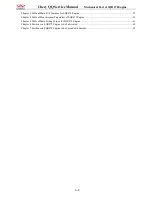
Summary of Contents for 1100 GKE OutLaw
Page 1: ...Service Manual 1100GKE 4 4...
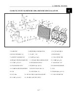
Page 62: ...4 COOLING SYSTEM 4 6 Cooling System Chart...
Page 158: ...10 CVT TRANSMISSION SYSTEM 10 7 5 Appearance installation dimension map Fan shaped array 10...
Page 165: ...11 EFI SYSTEM OF SQR 472ENGINE 11 3 3 The ECU control principle diagram...
Page 166: ...11 EFI SYSTEM OF SQR 472ENGINE 11 4 4 The ECU function module layout...
Page 260: ......

