© 2019 Polara Engineering, Inc. Doc. 350-058-01 Rev. C-25059 12/4/2018 Page 1 of 2
www.polara.com
Installation Quick Start Guide for iN3/iPHCU3W
AWG 18 wire is recommended for this installation and should meet all applicable regulatory requirements. Removing power from
the pedestrian signal head during installation is recommended for protection from electric shock.
Note: An iN2 PBS can operate as an iN3 PBS (standalone Ped-Head Based System). It comes with a 3-position teminal
block capable of connecting a 3-Wire Cable to a Ped-Head Control Unit. If changing an installed/existing iN2 PBS
to operate as an iN3, you must disconnect the ped wires in the cabinet from the Polara Interconnect Board and
land to standard ped input terminals.
Equipment needed for complete iN3:
iN3 Push Button Station
iPHCU3W (Ped Head Control Unit)
3-Wire Cable (Polara supplied or equiv.)
1. iN3
1.1 The iN3 PBS has two mounting holes vertically spaced at 6.0 inches. The mounting
is compatible with standard pushbutton frames with 6 inch mounting holes and
a wiring hole about 3.5 inches below the lower mounting hole. The suggested
mounting height is 42 inches from ground level to the center of the arrow button. The
iN3 PBS must be mounted only in the normal upright orientation, with the connection
terminals at the bottom. Any other mounted orientation will void the warranty as
moisture could collect inside the unit.
1.2
Before mounting the PBSs on their poles, go to the traffic signal controller cabinet
and set the PED phases to recall. Remove existing buttons/frames from poles.
Check holes for mounting fit and drill and tap ¼-20 as needed. Route the iN3-Cable
(General Cable C2831A or equiv.) between the pedestrian signal head and the pole.
1.3
If the PBS has a label with street names, the first name (before @) indicates the
street being crossed. Locate the unit in accordance with the label.
1.4 Remove 3 screws from the lower cover surrounding the pushbutton using a Torx
T15 driver bit. Lift off the lower cover. Remove all screws securing the sign and sign
plate if present. Verify the arrow on the button is oriented toward the associated
crosswalk. If necessary, the button / diaphragm assembly may be pulled off and
rotated as needed.
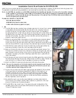
1.5 With the sign and lower cover removed, position the PBS against the pole and route
the wires forward through the opening at the bottom end of the module. Position the
wire such that 3 or 4 inches of wire is available at the bottom of the PBS.
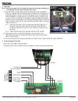
1.6
Attach the PBS to the pole using the provided ¼-20 bolts with washers.
Note: The use of a speed wrench or short socket is recommended. Insert the bot-
tom bolt with washers on bolt before holding the
iN3 PBS to
the pole to pre-
vent the washers from falling into the unit.
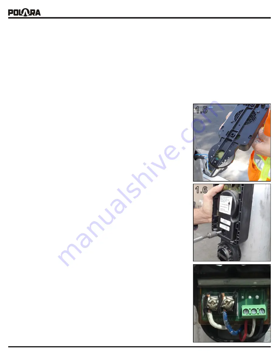
1.7
Connect the two wires from the traffic signal cabinet (if available) to the terminals
of the larger black terminal block labeled BUTTON/PLC. Wire polarity is not
important. Connect the 3-wire cable to the terminal block on the right. Make
sure the wiring matches at both ends according to the Data, GND, and PWR
labels at the terminals. With the power on, check that the PBS is operational.
Recheck tightness of all connections.
1.8 Re-install the lower cover and the sign. Additional environmental protection
for the sign can be gained by adding rubber washers or grommets on the sign
screws, or with the use of a silicone sealant.
1.9
The iN3 PBS is now ready to use. For programming and configuration of the
iN3 PBS, please refer to the “Polara iOS Field Service App User Guide” or the
“Polara PC App User Guide”.
1.5
1.6
1.7


