background image

107

MAINTENANCE AND LUBRICATION

PVT System

WARNING

The PVT system rotates at high speeds, creating large amounts

of force on clutch components. Extensive engineering and

testing has been conducted to insure the safety of this product.

However, as the owner you have the following responsibilities to

make sure this system remains safe:

D

Do not modify any component of the PVT system. Doing so may

reduce its strength so that a failure may occur at high speeds.

This system has been precision balanced. Any modification will

cause the system to be out of balance, creating vibration and

additional loads on components.

D

Routine maintenance is the responsibility of the owner. Always

follow recommended maintenance procedures. See your deal-

er!

D

This PVT system is intended for use on Polaris products only.

D

The PVT housing must be securely in place during operation.

Failure to comply with this warning can result in severe injury

or death.

Summary of Contents for 2002 Sportsman 6x6

Page 1: ......

Page 2: ...WARNING The engine exhaust from this product contains chemicals known to cause cancer birth de fects or other reproductive harm...

Page 3: ...Indicates a potential hazard that could result in serious injury or death WARNING...

Page 4: ...ted a web site just for YOU S Technical tips S New product introductions S Event schedules S Parts and Service Manual information S Exciting details about The Way Out Check it out www polarisindustrie...

Page 5: ...for safe and enjoyable operation of your vehicle Your Owner s Manual contains instructions for minor maintenance Major repairs are covered in the Polaris Service Manual and should be performed by a Fa...

Page 6: ...TRAINING When you purchased this vehicle your dealer offered a hands on safety training course covering all aspects of vehicle safety In addition you were provided with certain printed material which...

Page 7: ...Safety Issues 8 Decals and Locations 13 Operator Safety 21 Controls and Features 37 49 Controls 37 Features 47 Operation 50 56 Pre Ride 50 Vehicle Break In Period 51 Starting the Engine 52 Carrying L...

Page 8: ...Lubrication Recommendations 77 Maintenance Record 85 Cooling System 86 Filter Systems 88 Adjustments 90 Spark Plugs 103 Spark Arrestor 104 Recoil Housing 106 PVT 107 Battery 108 Lights 111 Cleaning an...

Page 9: ...tant for model identification when registering your vehicle obtaining insurance or whenever replacement parts are required In the event your vehicle were stolen these numbers are essential to the reco...

Page 10: ...manual The safety alert symbol on your vehicle or in this manual alerts you to the potential for personal injury Indicates a potential hazard that could result in serious injury or death Indicates a p...

Page 11: ...ilable at the time of printing Polaris Industries Inc reserves the right to make product changes and improvements which may affect illustrations or explanations No part of this manual shall be reprodu...

Page 12: ...uld also wear eye protection goggles or face shield gloves boots long sleeved shirt or jacket and long pants S Never consume alcohol or drugs before or while operating this ve hicle S Never operate at...

Page 13: ...ehicle around on any hill until you have mastered the turning technique described in this manual on level ground Avoid crossing the side of a steep hill if possible S Always use proper procedures if y...

Page 14: ...general public Polaris hereby strongly recommends and requests that consumers not have installed on a Polaris 6x6 any equipment which is intended to increase the speed or power of the vehicle or make...

Page 15: ...an National Standards Institute label ANSI Z90 1 or the Snell Memorial Foundation label 2 Eye Protection Do not depend on sunglasses for proper eye protection A pair of goggles or helmet face shield o...

Page 16: ...or a replacement Any safety decal needing replacement will be provided by Polaris at no charge The part number is printed on the decal The addition of certain accessories including but not limited to...

Page 17: ...CAPACITY Gross Vehicle Weight INCLUDING MACHINE DRIVER AND CARGO IS 1965 LBS Reduce speed and allow greater distance for braking when carrying cargo Overloading or carrying tall off center or unsecur...

Page 18: ...15 SAFETY Safety Decals and Locations 3...

Page 19: ...WAYS D Use an approved HELMET AND PROTECTIVE GEAR D Avoid paved surfaces Pavement may seriously affect handling and control D Use proper RIDING TECHNIQUES to avoid vehicle overturns on hills and rough...

Page 20: ...17 SAFETY Safety Decals and Locations 4 5 6 7 8...

Page 21: ...ove flammable containers from box before refueling Maximum Box Load 800 lbs S Passengers can be thrown off This can cause serious injury or death S Never carry passengers ALL WHEEL DRIVE SWITCH Do not...

Page 22: ...belt clutch guard To prevent serious injury do not operate vehicle with guard removed Do not modify engine or clutch Doing so can cause part failure possible imbalance and excessive engine RPM which c...

Page 23: ...ment will severely damage the engine D Clean air filter often more frequent cleaning required in dusty conditions D Operation of this vehicle without engine breather filter s can cause engine damage C...

Page 24: ...operating techniques described in the Owner s Manual For more information about the training course contact an authorized Polaris dealer or call Polaris at 1 800 342 3764 POTENTIAL HAZARD Failure to f...

Page 25: ...g this vehicle on paved surfaces WHAT CAN HAPPEN This vehicle s tires are designed for off road use only not for use on pavement Paved surfaces may seriously affect handling and control of the vehicle...

Page 26: ...Operating this vehicle without wearing an approved helmet eye protection and protective clothing WHAT CAN HAPPEN Operating without an approved helmet increases your chances of a severe head injury or...

Page 27: ...n rolling backwards Keep weight uphill never apply engine power Never apply the rear brake while rolling backwards Apply the service brake gradually When fully stopped apply auxiliary brake as well an...

Page 28: ...Always travel at a speed which is proper for the terrain visibility and operating conditions and your experience WARNING WARNING POTENTIAL HAZARD Improperly operating in reverse WHAT CAN HAPPEN You c...

Page 29: ...s and schedules described in the Owner s Manual POTENTIAL HAZARD Removing hands from handlebars or feet from footrests during operation WHAT CAN HAPPEN Removing even one hand or foot can reduce your a...

Page 30: ...HAZARD Go slowly and be extra careful when operating on unfamiliar terrain Always be alert to changing terrain conditions when operating the vehicle WARNING WARNING POTENTIAL HAZARD Skidding or slidin...

Page 31: ...uld cause loss of traction or vehicle control which could result in an accident including an overturn HOW TO AVOID THE HAZARD Do not operate on excessively rough slippery or loose terrain until you ha...

Page 32: ...low speeds before attempting to turn at faster speeds Do not turn at excessive speed POTENTIAL HAZARD Operating on excessively steep hills WHAT CAN HAPPEN The vehicle can overturn more easily on extre...

Page 33: ...in the Owner s Manual See pages 62 through 67 Always check the terrain carefully before you start up any hill Never climb hills with excessively slippery or loose surfaces Shift your weight forward N...

Page 34: ...going down hills as described in the Owner s Manual See page 65 NOTE A special technique is required when braking as you go downhill Always check the terrain carefully before you start down any hill...

Page 35: ...y hill until you have mastered the turning technique as described in the Owner s Manual on level ground See pages 62 and 67 Be very careful when turning on any hill Avoid crossing the side of a steep...

Page 36: ...r procedures as described in the Owner s Manual on page 71 WARNING WARNING POTENTIAL HAZARD Overloading this vehicle or carrying or towing cargo improperly WHAT CAN HAPPEN Could cause changes in vehic...

Page 37: ...ing water or in water deeper than that specified in your Owner s Manual See page 68 Remember that wet brakes may have reduced stopping ability Test your brakes after leaving water If necessary apply t...

Page 38: ...re as described in the Owner s Manual See page 96 POTENTIAL HAZARD Operating this vehicle with improper modifications WHAT CAN HAPPEN Improper installation of accessories or modification of this vehic...

Page 39: ...you are sure the ice is thick enough and sound enough to support the machine and its operator as well as the force that is created by a moving vehicle POTENTIAL HAZARD Operating this vehicle after co...

Page 40: ...ontrols Sportsman 6x6 Vehicle Nomenclature 6 Floor Boards 7 Back Rest 8 Bed 9 Front Rack 1 Service Brake Lever 2 Middle Axle Auxiliary Brake 3 Throttle Lever 4 Bed Dump Latch Release s 5 Gearbox Shift...

Page 41: ...st the on position Release the key when the engine starts This switch must be turned clockwise to the on position to start the engine 3 Engine Stop Switch The engine will not start or run when the swi...

Page 42: ...during starting 1 2 The Electronic Throttle Control ETC limits engine power in the event of a throttle system malfunction and is provided for your safety Do not attempt to modify the ETC system or rep...

Page 43: ...h are activated by one lever only Always test brake lever travel and reservoir fluid level before riding When squeezed the lever should feel firm Any sponginess would indicate a possible fluid leak or...

Page 44: ...Brakes front wheel and transmission Left Handlebar Lever This lever controls braking action to all six wheels It is the normal service brake system to use for braking 2 Auxiliary Brakes Right Handleba...

Page 45: ...tended for more than five minutes Do not depend on parking brake to hold vehicle for more than five minutes 3 WARNING Always check to be sure that the parking brake has been disengaged before operatin...

Page 46: ...M 2 octane The fuel tank supply valve 2 located on the left side of the vehicle has three positions OFF For vehicle storage and whenever transporting ON For normal operation RES For reserve supply in...

Page 47: ...ames or sparks in or near the area where refueling is performed or where gasoline is stored D Do not over fill the tank Do not fill the tank neck D If you should get gasoline on your skin or clothing...

Page 48: ...idling move the lever to the desired gear Do not attempt to shift gears with engine speed above idle or while the vehicle is moving Always place the transmission in gear with the parking brake locked...

Page 49: ...page 42 2 Grasp the recoil starter tightly and pull slightly un til the starter mechanism engages 3 Pull the rope abruptly to start the engine Recoil Starter Do not extend the starter rope so far tha...

Page 50: ...icator Green 6 All Wheel Drive indicator Red 7 Engine hi temp warning indicator Red NOTE Will light only if engine overheats With engine running verify function of indicator lights each time vehicle i...

Page 51: ...he switch is off the 6x6 is in rear wheel drive at all times When the switch is on the 6x6 is in AWD and the front wheels will automatically engage anytime the rear wheels lose traction When the rear...

Page 52: ...if the handlebars pull to one side If both front wheel hubs are engaged steering effort increases but remains balanced from left to right and vehicle speed is somewhat restricted CAUTION Do not switch...

Page 53: ...which is open and will give you room to familiarize yourself with vehicle operation and handling 4 Vary the throttle positions Do not operate at sustained idle 5 Perform regular checks on fluid levels...

Page 54: ...el in cludes auxiliary brake D Throttle check for free operation and closing D Headlight Taillight Brakelight check operation of all indicator lights and switches D Engine stop switch check for proper...

Page 55: ...ter for a maximum of five seconds releasing the key or button when the vehicle starts If engine does not start release the starter and wait five seconds then activate the starter for another five seco...

Page 56: ...e fuel tank valve to ON 4 Sit on the vehicle 5 If the engine has cooled to a point where it does not readily start inter mittent use of the choke button pulled half way out is permitted 6 If the engin...

Page 57: ...lbs 34 kg 800 lbs 363 kg Improper loading of the front rack can obstruct the headlight beam reducing night visibility Do not obstruct the headlight beam with cargo Maximum Towing Capacities Level Grou...

Page 58: ...in the cargo bed as possible D Reduce speed and allow greater distance for braking D Heavy loads can cause braking and control problems D Use extreme caution when applying brakes with a loaded ve hicl...

Page 59: ...to dump WARNING Never carry passengers on the bed If the weight distribution on the bed is located toward the rear of the bed and the release lever is pulled forward the bed will want to dump on its...

Page 60: ...TS PRESUMED TO CONSTITUTE TAMPERING ARE THE ACTS LISTED BELOW 1 Removal or alteration or the puncturing of the muffler or any engine component which conducts removal of engine exhaust gases 2 Removal...

Page 61: ...l in cludes auxiliary brake D Throttle check for free operation and closing D Headlight Taillight Brakelight check operation of all indicator lights and switches D Engine stop switch check for proper...

Page 62: ...ust be securely latched before loading and operating Unintentional bed tilting will result if weight is placed in the rear of the bed and the latch is not secured Maximum Front Rack 75 lbs 34 kg Maxim...

Page 63: ...ngs and determine your path of travel 4 Release the parking brake 5 Slowly depress the throttle with your right thumb and begin driving Vehicle speed is controlled by the amount of throttle opening an...

Page 64: ...heel when turning and the inside tire must slip traction slightly To turn steer in the direction of the turn leaning your upper body to the inside of the turn while supporting your weight on the outer...

Page 65: ...oward the hill while keeping your feet on the footrests 3 Steer slightly into the hill to maintain vehicle directions If vehicle begins to tip quickly turn the front wheel downhill if possible or dism...

Page 66: ...kid by turning the handlebars in thedirection ofthe skid and shifting your body weight forward 4 Driving with Demand 6 Drive All Wheel Drive engaged can assist in controlling the vehicle in slippery a...

Page 67: ...ippery surfaces can be dangerous Loss of tire traction and vehicle control can result in an accident including an overturn S Never apply brakes during a skid Complete loss of control can result S Do n...

Page 68: ...hill always 1 Drive directly downhill 2 Transfer your weight to the rear of the vehicle 3 Slow down 4 Apply the brakes slightly to aid in slowing WARNING Loss of vehicle control due to excessive speed...

Page 69: ...ate of speed and throttle opening 5 Remain alert and be prepared to take emergency action This may in clude quick dismounting of the vehicle 15_ Maximum WARNING Braking and handling are greatly affect...

Page 70: ...bars full right facing front of ve hicle 5 While holding service brake release parking brake lock and slowly al low vehicle to roll around to your right until it is pointing across the hill or slightl...

Page 71: ...brakes by applying light pressure to the lever until braking action is normal S Avoid operating the 6X6 through deep or fast flowing water If you cannot avoid water which exceeds the recommended maxim...

Page 72: ...is open Loss of control may result NOTE This vehicle is equipped with a reverse speed limiter The override button should be used with caution as rearward vehicle speed is greatly increased Do not oper...

Page 73: ...nd you or the vehicle could tip over on a steep incline causing severe injury or death Always back slowly avoiding excessive speed and do not use the reverse speed override switch system unless additi...

Page 74: ...right side of the trail if possible and be constantly alert for hazards such as logs rocks and low hanging branches WARNING Hidden or unseen hazards on the trail can be dangerous Personal injury or th...

Page 75: ...RNING Always check to be sure that the parking brake has been disengaged before operating the vehicle An accident could result if the parking brake is left on while the vehicle is operated The parking...

Page 76: ...aintenance a tool kit is provided in the storage compartment under the seat Items included in the kit are S screwdriver S open end wrench 8 10 mm S open end wrench 12 14 mm S box end wrench S tire pre...

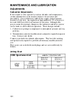
Page 77: ...r replacement parts Always use genuine Polaris parts available from your Polaris dealer Item Hours or Odometer Frequency Remarks Headlamp Inspection Pre ride Pre ride Check operation daily apply Polar...

Page 78: ...r Float Bowl 50 hrs 6 months Drain bowl periodically and prior to storage Engine Oil Level Change 100 hrs 1000 miles 6 months Check Level Daily Break in Service at 1 month Change oil more often in col...

Page 79: ...Engine Mounts 100 hrs 12 months Inspect Spark arrestor 100 hrs 12 months Clean out Spark Plug 100 hrs 12 months Inspect replace if necessary Front hubs fluid change 100 hrs 12 months J Clutches drive...

Page 80: ...ear Selector 10 W Non detergent Oil Maintain oil level at the center of the shift rail Do not overfill Change every 2 years or 200 hours Transmission Oil Polaris Premium Synthetic gearcase lube Fill t...

Page 81: ...ll Joint Grease Locate zerk on back side of struts and grease with grease gun Every 3 months or at 50 hrs Front A Arm Pivot Shaft Grease Locate zerk on pivot shaft and grease with grease gun Every 3 m...

Page 82: ...fitting on eccentric and grease with grease gun Every 3 months or 50 hrs Center Swing Arm Housing Grease Locate fitting on swing arm housing and grease with grease gun Every 3 months or 50 hrs Rear St...

Page 83: ...is correct when it reaches the bottom of the filler hole The correct transmission lubricant to use is Polaris Premium Synthetic Gearcase Lubricant PN 2871478 Transmission Oil Changing Procedure 1 Rem...

Page 84: ...level surface remove fill plug and check the lubricant level Lubricant should be kept at the bottom of fill plug thread The correct gearcase lubricant to use is GL5 80 90 Weight Gear Lube Gearcase Oil...

Page 85: ...is Premium 4 is not used You will also need to follow the manufacturers recommendations for ambient temperature operation Oil System The oil tank is located on the left side of the vehicle To check th...

Page 86: ...cle on a level surface 2 Clean area around drain plug at the bottom of the oil tank 3 Place a drain pan beneath the oil tank and remove the drain plug 4 Allow oil to drain completely 5 Install a new s...

Page 87: ...mately 1 cup of engine oil will remain in the crankcase To drain remove drain plug found on lower right side of crankcase NOTE The sealing surfaces on the drain plug and crankcase should be clean and...

Page 88: ...UBRICATION Periodic Maintenance Record Use the following chart to record periodic maintenance work Maintenance Interval Performed Servicing Date Servicing Dealer or Person Remarks First 5 Hrs 25 Hrs 5...

Page 89: ...rrect replacement part To insure that the coolant maintains its ability to protect the engine it is recommended that the system be completely drained every two years and a fresh mixture of antifreeze...

Page 90: ...ses the contracting cooled coolant is drawn back up from the bottle past the pressure cap and into the radiator NOTE Some coolant level drop on new machines is normal as the system is purging itself o...

Page 91: ...ps securing the airbox lid and remove lid 3 Loosen clamp and remove filter 4 Removefabrictypepre filterfrom main filter Wash pre filterinsoapy water and dry it 5 Reinstall pre filter over main filter...

Page 92: ...the engine 2 Inspect filter for debris Blow through gently in direction of arrow on filter to check for clogging Replace as needed 3 Check hoses for cracks deterioration abrasion or leaks Replace as n...

Page 93: ...t straight back from the steering post 2 Place stands in front of the ma chine perpendicular to the rear tires 3 Tie an elastic string around the stands making sure string just touches side surface of...

Page 94: ...dlebar adjuster block bolts to 10 to 12 ft lbs Optional Suspension Springs Although your Polaris 6x6 suspension has the capability of providing you with the best ride possible the following accessory...

Page 95: ...uate level see page 40 Normal func tioning of the diaphragm is to extend into the reser voir as fluid level drops If the fluid level is low and the diaphragm is not extended a leak is indi cated and t...

Page 96: ...which activates the front brake system The transmission brake system is self adjusting and requires no maintenance other than periodic checks of the pads for wear Wear Line S Pads should be changed w...

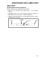
Page 97: ...Slide the bolts off inline cable adjuster sleeve Loosen adjuster locknut 2 Turn adjuster until 1 16 to 1 8 freeplay is achieved at thumb lever Flip throttle lever several times to confirm adjustment 3...

Page 98: ...e correct position on the wheel hub Be sure the valve stem is toward the outside and rotation ar rows on the tire point toward forward rotation 2 Attach the wheel nuts and fin ger tighten them 3 Lower...

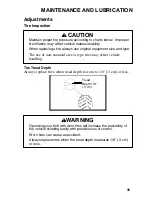
Page 99: ...may affect vehicle maneuverability When replacing a tire always use original equipment size and type The use of non standard size or type tires may affect vehicle handling Tread Depth 1 8I 3 cm WARNI...

Page 100: ...ing vehicle driver and cargo Vehicle weighs 895 lbs 406 kg The following items should be checked occasionally for tightness or if they have been loosened for maintenance service Axle and Wheel Nut Tor...

Page 101: ...b and into the ec centric axle housing 5 Roll the vehicleahead orback to adjust chain slack to the proper dimension 6 Tighten caliper mount bolts 10 12 ft lbs 1 4 1 7 kg m 7 Tighten the eccentric lock...

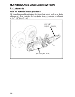
Page 102: ...ents Rear Axle Drive Chain Adjustment All procedures used in adjusting the front chain apply to the rear chain adjustment Total slack for the rear chain however should be adjusted to 1 4 1 2 6 1 3 cm...

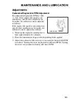
Page 103: ...he engine idle speed is not satisfactory and all other conditions are favorable the carburetor can be adjusted as follows 1 Warm up the engine by running the ve hicle approximately five minutes 2 Plac...

Page 104: ...rive system can be made to allow efficient operation These changes include 1 Carburetor re jetting to compensate for atmospheric pressure and oxy gen loss 2 Transmission convertor modification to adju...

Page 105: ...panel behind the fuel tank With a quick and firm motion push down on the side panel to disengage the top rear two tabs Then pull up on side panel to disengage front upper and lower tab 4 To reinstall...

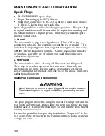
Page 106: ...aused by use of an improper spark plug or incorrect carburetion adjustments 2 Wet Fouled The insulator tip is black A damp oil film covers the firing end There may be a carbon layer over the entire no...

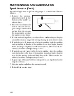
Page 107: ...fire hazard make sure that there are no combustible materials in the area when purging the spark arrestor S Wear eye protection S Do not stand behind or in front of the vehicle while purging the carb...

Page 108: ...re times 4 If particles are still suspected to be in the muffler back the machine onto an incline so the rear of the machine is one foot higher than the front Set the parking brake and block the wheel...

Page 109: ...screw once housing has been drained Water will enter the recoil housing if the starter handle is disengaged from the rope guide when under water After travelling in wet areas the recoil housing and st...

Page 110: ...the PVT system Doing so may reduce its strength so that a failure may occur at high speeds This system has been precision balanced Any modification will cause the system to be out of balance creating...

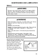
Page 111: ...situation could result causing serious injury or death WARNING Battery electrolyte is poisonous It contains sulfuric acid Serious burns can result from contact with skin eyes or clothing Antidote Exte...

Page 112: ...e of corrosion If cleaning is necessary remove the corrosion with a stiff wire brush Wash with a solution of one tablespoon baking soda and one cup water Rinse well with tap water and dry off with cle...

Page 113: ...hold down strap 6 Verify that cables are properly routed NOTE S When your ATV is placed in storage for three months or more the battery should be removed charged to proper level and stored in a cool...

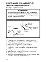
Page 114: ...pod cover 5 Unplug headlamp from wiring harness 6 Remove boot and locking collar from back of lamp housing 7 Grasp base of lamp and lift it out 8 Reverse previous steps to replace lamp and reassemble...

Page 115: ...h the headlight approximately 25 7 6 m from a wall 2 Measure the distance from the floor to the center of the headlight and make a mark on the wall at the same height 3 Start the engine and turn the h...

Page 116: ...back of headlight pod 3 Lift pod cover up Disconnect speedometer harnesses from speedometer Unplug indicator light harness and remove pod cov er 4 Unplug headlamp from wiring har ness 5 Remove O Ring...

Page 117: ...he harness and replace it with the recom mended lamp 4 Test the taillight brakelight to see that it s working 5 Replace the lamp harness into the back of the taillight assembly twist ing 1 4 turn to l...

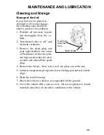
Page 118: ...e chain wheel bearings transmission seals body panels brakes and warning labels Many expensive repair bills can result from using high pressure detergent systems The best and safest way to clean your...

Page 119: ...plug and pour approximately one ounce of Premium 4 oil into the cylin der Operatethestarterfor afew seconds and reinstall the spark plug 4 Remove the battery Store it in a cool dry place out of the s...

Page 120: ...the fuel valve to off 2 Be certain the fuel cap and oil cap are installed correctly 3 Always tie the vehicle to the transporting unit securely using suitable straps and or rope 4 Always place the tran...

Page 121: ...Rear Brake Fixed Disc Hydraulic Floating Caliper Auxiliary Brake Fixed Disc Hydraulic Floating Caliper Fuel Capacity 4 25 U S Gal Engine Oil Capacity 2 U S Qts Headlight 12V 60W Taillight 12V 5W Exha...

Page 122: ...rting Electric Manual Ignition CDI Spark Plug BKR5E NGK Alternator 250W Comp Ratio 10 2 1 Full Stroke Timing 30 3500 Carburetion 1 BST34 CV Type Main Jet 142 5 Pilot Jet 40 Jet Needle 4HB41 3 Needle J...

Page 123: ...120 WIRING DIAGRAM...

Page 124: ...low RPM or low ground speed at approxi mately 3 7 MPH Drive at higher speed or use Low Range The use of Low Range is high ly recommended for cooler PVT oper ating temperatures and longer compo nent li...

Page 125: ...Shift the transmission to neutral Using the throttle vary the engine rpm from idle to full throttle Repeat several times as required During this proce dure the throttle should not be held at the full...

Page 126: ...tch Off No Fuel Water in Fuel Spark Plug Fuel Valve Off Drain System No Spark to Spark Plug Contact Your Dealer Clogged Fuel Valve ENGINE STOPS OR LOSES POWER No Fuel Contact Your Dealer Contact Your...

Page 127: ...y Registration Form will be the warranty entitlement If you have not signed the original registration and received the customer copy please contact your dealer immediately NO WARRANTY COVERAGE WILL BE...

Page 128: ...NTH WARRANTY PERIOD POLARIS FURTHER DISCLAIMS ALL EXPRESS WARRANTIES NOT STATED IN THIS WARRANTY Some states do not allow limitations on how long an implied warranty lasts so the above limitation may...

Page 129: ...ator Lights 47 Jetting Chart 101 Light Switches 47 Lights Adjustment Replacement 111 114 Load Distribution 59 Lubrication Recommendations 77 84 Main Switch 38 Maintenance And Lubrication 73 117 Mainte...

Page 130: ...7 INDEX Welcome 2 Wheel Installation 95 Wheel Removal 95 Wiring Diagram 120 Understanding Warnings 7 Vehicle Break in Period 50 Vehicle Identification Numbers 6 Vehicle Nomenclature 37 Warranty 124 12...

Page 131: ......
Reviews: