FUEL SYSTEM/CARBURETION
4.9
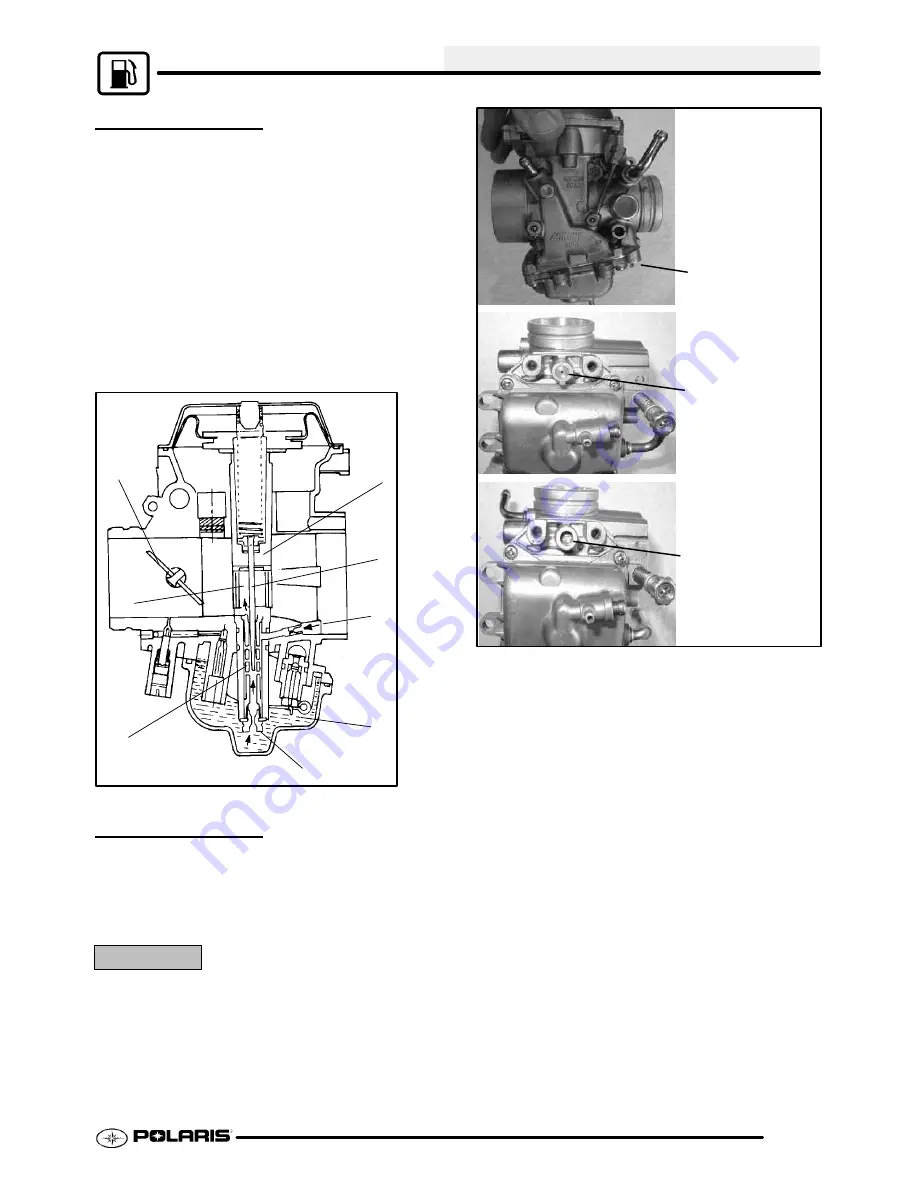
MAIN SYSTEM
As throttle valve (1) is opened, engine speed rises,
and this increases negative pressure in the venturi.
Consequently the vacuum slide (2) moves upward.
The fuel in float chamber (3) is metered by main jet (4),
and the metered fuel enters needle jet (5), in which it
mixes with the air admitted through main air jet (6) to
form an emulsion. The emulsified fuel then passes
through the clearance between needle jet (5) and jet
needle (7), and is discharged into the venturi (A).
Mixture proportioning is accomplished in needle jet
(5); the clearance through which the emulsified fuel
must flow is determined ultimately by throttle position
and vacuum slide height.
1
A
5
4
3
6
7
2
PILOT SCREW
The pilot system supplies fuel during engine operation
with the throttle valve closed or slightly opened. The
fuel/air mixture is metered by pilot screw and
discharged into the main bore through the pilot outlet.
CAUTION:
The pilot screw is calibrated at the factory to meet EPA / CARB
regulations for air quality standards and is sealed with a brass
plug to prevent tampering. Removal of the tamper proof plug
is not permitted. For service purposes, cleaning of the pilot
circuit can be done only by a certified repair shop to ensure air
quality standards are not exceeded.
Pilot Screw location
Brass Plug Installed
Brass Plug Removed
PartShark.com
877-999-5686
Summary of Contents for 2009 Trail Blazer 330
Page 94: ...ENGINE 3 48 NOTES P a r t S h a r k c o m 8 7 7 9 9 9 5 6 8 6 ...
Page 110: ...FUEL SYSTEM CARBURETION 4 16 NOTES P a r t S h a r k c o m 8 7 7 9 9 9 5 6 8 6 ...
Page 124: ...BODY STEERING SUSPENSION 5 14 NOTES P a r t S h a r k c o m 8 7 7 9 9 9 5 6 8 6 ...
Page 196: ...ELECTRICAL 10 4 REVERSE LIMIT SYSTEM P a r t S h a r k c o m 8 7 7 9 9 9 5 6 8 6 ...
Page 226: ...ELECTRICAL 10 34 NOTES P a r t S h a r k c o m 8 7 7 9 9 9 5 6 8 6 ...
Page 227: ...ELECTRICAL WIRING DIAGRAM 2009 TRAIL BOSS P a r t S h a r k c o m 8 7 7 9 9 9 5 6 8 6 ...
Page 228: ...ELECTRICAL WIRING DIAGRAM 2009 TRAIL BOSS P a r t S h a r k c o m 8 7 7 9 9 9 5 6 8 6 ...
Page 229: ...ELECTRICAL WIRING DIAGRAM 2009 TRAIL BLAZER P a r t S h a r k c o m 8 7 7 9 9 9 5 6 8 6 ...
Page 230: ...ELECTRICAL WIRING DIAGRAM 2009 TRAIL BLAZER P a r t S h a r k c o m 8 7 7 9 9 9 5 6 8 6 ...


