BRAKES
9.5
BRAKE NOISE
TROUBLESHOOTING
Dirt or dust buildup on the brake pads and disc is the
most common cause of brake noise (squeal caused
by vibration). If cleaning does not reduce the
occurrence of brake noise, Permatex
t
Disc Brake
Quiet can be applied to the back of the pads. Follow
directions on the package. This will keep pads in
contact with caliper piston(s) to reduce the chance of
squeaks caused by dirt or dust. See table on the next
page.
Brake Noise Troubleshooting
Possible Cause
Remedy
Dirt, dust, or im-
bedded material
on pads or disc
Spray disc and pads
with CRC Brake Kleen
t
or equivalent non-flam-
mable aerosol brake
cleaner. Remove pads
and/or disc hub to clean
imbedded material from
disc or pads.
Pad(s) dragging on
disc (noise or
premature pad wear)
Improper adjustment
Insufficient lever or
pedal clearance
Master cylinder res-
ervoir overfilled
Master cylinder
compensating port
restricted
Master cylinder pis-
ton not returning com-
pletely
Caliper piston(s) not
returning
Operator error (riding
the brake / park brake
applied)
Adjust pad stop
(front calipers)
Check position of
controls & switches.
Set to proper level
Clean compensating port
Inspect.
Repair as necessary
Clean piston(s) seal
Educate operator
Loose wheel hub or
bearings
Check wheel and hub
for abnormal
movement.
Brake disc warped or
excessively worn
Replace disc
Brake disc
misaligned or loose
Inspect and repair as
necessary
Noise is from other
source (chain, axle,
hub, disc or wheel)
If noise does not
change when brake is
applied check other
sources. Inspect and
repair as necessary
Wrong pad for
conditions
Change to a softer or
harder pad
HYDRAULIC
CALIPER BLEEDING
T
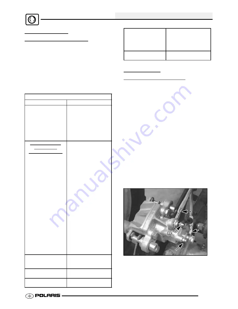
his caliper is a single piston design. The caliper
pistons are “T”-shaped, which allows both hand and
foot brake to use the same caliper piston, but remain
separated by seals. The hand brake system applies
hydraulic pressure to both front calipers and only the
outer diameter of the rear caliper pistons.
The
auxiliary (foot) brake applies pressure to the inner
portion of the rear caliper pistons. Because the hand
and foot brake hydraulic systems are separate, there
are also two bleed screws -- one for the outer fluid
chamber (hand brake), and one for the inner fluid
chamber (foot brake).
The basic procedure for
bleeding the brake system is the same as outlined in
this chapter, however, each system must be bled
separately.
Hydraulic Auxiliary Brake inspection and adjustment
is outlined in Chapter 2.
NOTE: Top (Uppermost) bleed screw (A) and brake
line (A) is for hand brake system
Lower screw (B) and brake line (B) is for auxiliary (foot)
brake system.
B
B
A
A
PartShark.com
877-999-5686
Summary of Contents for 2009 Trail Blazer 330
Page 94: ...ENGINE 3 48 NOTES P a r t S h a r k c o m 8 7 7 9 9 9 5 6 8 6 ...
Page 110: ...FUEL SYSTEM CARBURETION 4 16 NOTES P a r t S h a r k c o m 8 7 7 9 9 9 5 6 8 6 ...
Page 124: ...BODY STEERING SUSPENSION 5 14 NOTES P a r t S h a r k c o m 8 7 7 9 9 9 5 6 8 6 ...
Page 196: ...ELECTRICAL 10 4 REVERSE LIMIT SYSTEM P a r t S h a r k c o m 8 7 7 9 9 9 5 6 8 6 ...
Page 226: ...ELECTRICAL 10 34 NOTES P a r t S h a r k c o m 8 7 7 9 9 9 5 6 8 6 ...
Page 227: ...ELECTRICAL WIRING DIAGRAM 2009 TRAIL BOSS P a r t S h a r k c o m 8 7 7 9 9 9 5 6 8 6 ...
Page 228: ...ELECTRICAL WIRING DIAGRAM 2009 TRAIL BOSS P a r t S h a r k c o m 8 7 7 9 9 9 5 6 8 6 ...
Page 229: ...ELECTRICAL WIRING DIAGRAM 2009 TRAIL BLAZER P a r t S h a r k c o m 8 7 7 9 9 9 5 6 8 6 ...
Page 230: ...ELECTRICAL WIRING DIAGRAM 2009 TRAIL BLAZER P a r t S h a r k c o m 8 7 7 9 9 9 5 6 8 6 ...


