ELECTRICAL
10.26
HEADLIGHT ADJUSTMENT
The headlight beam can be adjusted up and down and
side to side.
1.
Place the vehicle on a level surface with the
headlight approximately 25’ (7.6 m) from a wall.
25’ (7.6 m)
Lamp Center Height
2
″
(5.1 cm)
2.
Measure the distance from the floor to the center
of the headlight and make a mark on the wall at
the same height.
3.
Shift transmission to neutral, start the engine and
turn the headlight switch to high beam.
4.
Observe headlight aim. The most intense part of
the headlight beam should be aimed 2
″
(5.1 cm)
below the mark placed on the wall in Step 2.
NOTE: Rider weight must be included on the
seat.
For machines with separate low beam
lights, the drop should be 8
″
(20.3 cm) in 25’.
5.
Adjust beam to desired position by moving
headlight.
HEADLIGHT LAMP
REPLACEMENT
NOTE: Allow lamp to cool before proceeding. Do not
touch a halogen lamp with bare fingers. Oil from your
skin leaves a residue, causing a hot spot which will
shorten the life of the lamp. Hold the bulb by the base
only.
Headlight Assembly Removal
1.
Carefully unsnap the electrical harness from the
back of the headlight assembly and remove the
harness.
2.
Remove the screws and nuts from the sides of the
headlight assembly.
3.
Remove the headlight assembly.
Headlamp Replacement
1.
With the headlight assembly in place, unsnap the
electrical harness from the back the headlight
assembly.
2.
Turn and pull out the connector on the back of the
headlight assembly. Gently pull the bulb out and
replace with the new bulb. Snap the harness back
into place.
TAILLIGHT/BRAKELIGHT
LAMP REPLACEMENT
If the taillight/brakelight does not work the lamp may
need to be replaced.
1.
From the rear of the taillight remove two screws
holding lens cover in place and remove lens
cover.
Lens Cover
Bulb
2.
Remove lamp and replace it with recommended
lamp. Apply Dielectric Grease (PN 2871329).
3.
Reinstall the lens cover removed in Step 1.
4.
Test the taillight/brakelight to see that it’s working.
POD ASSEMBLY REMOVAL /
INDICATOR LAMP
REPLACEMENT
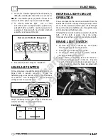
1.
Remove the two screw covers (A) and screws
from the pod assembly (B).
A
B
C
PartShark.com
877-999-5686
Summary of Contents for 2009 Trail Blazer 330
Page 94: ...ENGINE 3 48 NOTES P a r t S h a r k c o m 8 7 7 9 9 9 5 6 8 6 ...
Page 110: ...FUEL SYSTEM CARBURETION 4 16 NOTES P a r t S h a r k c o m 8 7 7 9 9 9 5 6 8 6 ...
Page 124: ...BODY STEERING SUSPENSION 5 14 NOTES P a r t S h a r k c o m 8 7 7 9 9 9 5 6 8 6 ...
Page 196: ...ELECTRICAL 10 4 REVERSE LIMIT SYSTEM P a r t S h a r k c o m 8 7 7 9 9 9 5 6 8 6 ...
Page 226: ...ELECTRICAL 10 34 NOTES P a r t S h a r k c o m 8 7 7 9 9 9 5 6 8 6 ...
Page 227: ...ELECTRICAL WIRING DIAGRAM 2009 TRAIL BOSS P a r t S h a r k c o m 8 7 7 9 9 9 5 6 8 6 ...
Page 228: ...ELECTRICAL WIRING DIAGRAM 2009 TRAIL BOSS P a r t S h a r k c o m 8 7 7 9 9 9 5 6 8 6 ...
Page 229: ...ELECTRICAL WIRING DIAGRAM 2009 TRAIL BLAZER P a r t S h a r k c o m 8 7 7 9 9 9 5 6 8 6 ...
Page 230: ...ELECTRICAL WIRING DIAGRAM 2009 TRAIL BLAZER P a r t S h a r k c o m 8 7 7 9 9 9 5 6 8 6 ...


