ENGINE
3.45
8.
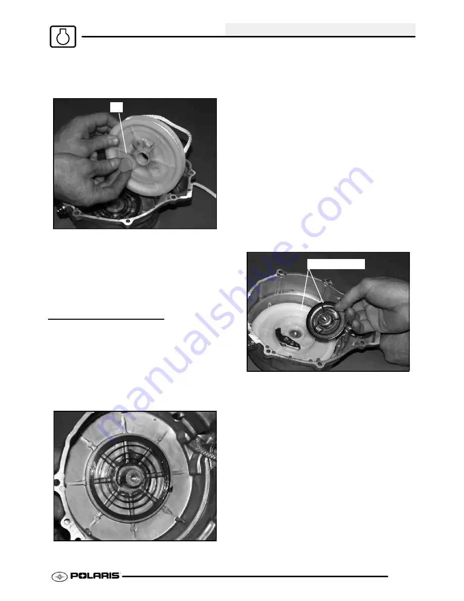
Slowly and carefully remove reel from recoil
housing making sure the spring remains in the
housing. Inspect the reel hub and bushing (A) for
wear.
A
9.
Unwind rope and inspect for cuts or abrasions.
10. Inspect drive tab on hub return spring for damage.
To remove hub return spring, hold outer coils in
place with one hand and slowly remove spring
one coil at a time from the inside out.
11. Pull knot out of of recoil reel. Untie knot. Remove
rope from reel.
RECOIL ASSEMBLY
CAUTION: Recoil is under spring tension. A face
shield or eye protection is required during this
procedure.
To install a new spring:
1.
Place spring in housing with the end positioned so
the spring spirals inward in a counterclockwise
direction. See photo.
2.
Hold spring in place and cut retaining wire.
To reinstall an old spring:
1.
Hook outer tab in place in recoil housing and wind
spring in a counterclockwise direction one coil at a
time while holding the installed coils in place.
2.
Lubricate the spring with light lubricant such as
Premium All Season Grease.
To complete recoil assembly:
1.
Route rope through guide bushing in recoil
housing and into reel. Tie a secure knot in end of
the rope.
2.
Wind rope counterclockwise onto the reel, as
viewed from ratchet side of reel.
3.
Lock rope into notch on outer edge of reel.
4.
Apply a small amount of grease or equivalent to
the center post of the housing and the bushing.
5.
Install reel into housing making sure the spring
drive tab on the reel engages the spring and the
reel is fully seated in the housing.
Open end here
6.
Apply downward pressure on the reel and rotate
counterclockwise approximately 6-7 turns to
pre-wind
the
spring.
Continue
rotating
counterclockwise until rope on outer edge aligns
with rope guide bushing.
7.
Release rope from notch and allow reel to rewind
completely. If more pre-wind is required, place rope
in notch and add additional turns of pre-wind.
8.
Install ratchet pawl and return spring, with long leg
of spring engaged in reel.
9.
Reinstall friction plate.
NOTE: The friction plate must be positioned with
both end tabs of the friction spring opposite the
ratchet pawl.
10. Torque friction plate retaining bolt to 5-6 ft. lbs.
(7-9 Nm).
11. Apply Crankcase Sealant (PN 2871557) to the
recoil housing outer edge. Reinstall recoil housing.
Seal stator wire harness grommet with RTV
silicone.
PartShark.com
877-999-5686
Summary of Contents for 2009 Trail Blazer 330
Page 94: ...ENGINE 3 48 NOTES P a r t S h a r k c o m 8 7 7 9 9 9 5 6 8 6 ...
Page 110: ...FUEL SYSTEM CARBURETION 4 16 NOTES P a r t S h a r k c o m 8 7 7 9 9 9 5 6 8 6 ...
Page 124: ...BODY STEERING SUSPENSION 5 14 NOTES P a r t S h a r k c o m 8 7 7 9 9 9 5 6 8 6 ...
Page 196: ...ELECTRICAL 10 4 REVERSE LIMIT SYSTEM P a r t S h a r k c o m 8 7 7 9 9 9 5 6 8 6 ...
Page 226: ...ELECTRICAL 10 34 NOTES P a r t S h a r k c o m 8 7 7 9 9 9 5 6 8 6 ...
Page 227: ...ELECTRICAL WIRING DIAGRAM 2009 TRAIL BOSS P a r t S h a r k c o m 8 7 7 9 9 9 5 6 8 6 ...
Page 228: ...ELECTRICAL WIRING DIAGRAM 2009 TRAIL BOSS P a r t S h a r k c o m 8 7 7 9 9 9 5 6 8 6 ...
Page 229: ...ELECTRICAL WIRING DIAGRAM 2009 TRAIL BLAZER P a r t S h a r k c o m 8 7 7 9 9 9 5 6 8 6 ...
Page 230: ...ELECTRICAL WIRING DIAGRAM 2009 TRAIL BLAZER P a r t S h a r k c o m 8 7 7 9 9 9 5 6 8 6 ...


