Instr 9927471
Rev 01 2016-11
Page 7 of 13
TORQUE
4ft. lbs. (5.4 Nm)
CONTROL BOX INSTALLATION
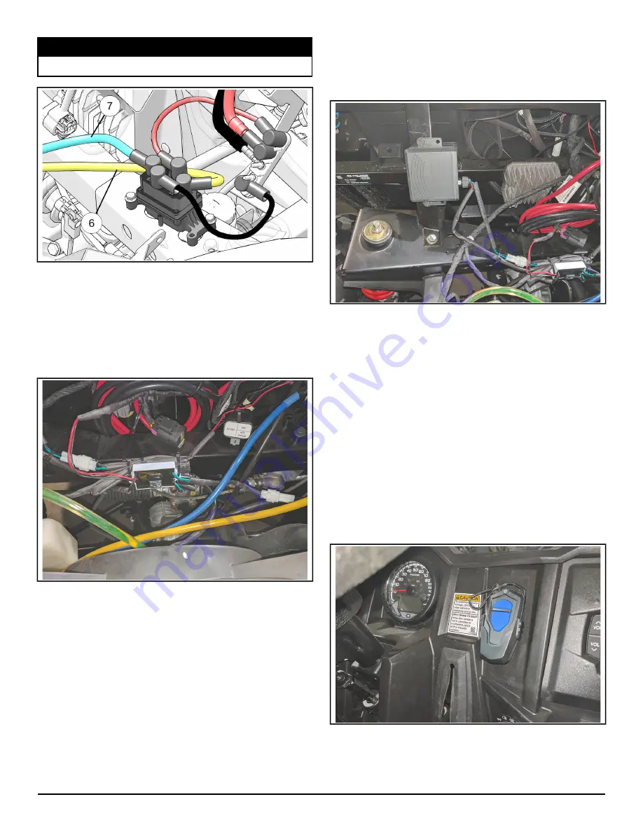
1. Position control as shown behind the radiator and
fasten to chassis with supplied cable ties as
shown. Connect white electrical connectors for the
control box as seen in the top photo of the
Electrical Connections Reference Guide section of
your instructions.
2. Route power wires from control box to bus bar and
connect red positive (+) (or orange depending on
the date your accessory kit was built) power wire
from control box to orange, keyed power terminal
on the vehicles bus bar. Route black negative (-)
wires from control box
w
to black (ground)
terminal area on bus bar.
3. Secure all remaining wires to the to the vehicle at
this time using supplied cable ties.
WIRELESS REMOTE RECEIVER INSTALLATION
1. Mount wireless remote receiver onto chassis using
supplied screws as shown. Tighten screws until
snug. Do not overtighten.
2. Connect white electrical connectors from remote
receiver as seen in the top photo of the Electrical
Connections Reference Guide of the instruction
manual. Route remote receiver power wires to bus
bar area and connect red positive (+) power wire
to the keyed power terminal as shown and the
black negative (-) cable to the ground terminal.
3. Secure remaining power wires to bus bar using
existing fasteners.
4. Secure all remaining wires to vehicle main wire
harness using cable ties.
WIRELESS REMOTE HOLDER INSTALLATION
1. Wireless remote holder can be installed in desired
location on vehicle. See photo for possible
mounting location. Use screws supplied in the
wireless remote kit for holder installation.


