background image

Instr 9928521

Rev 01 2017-07

Page 6 of 8

RIGHT SIDE

a. Disconnect existing RIGHT front speaker

harness (GRAY wires) from corresponding
amplifier connector

L

.

b. Join connector 9A on GRAY wire splitter

harness

o

to amplifier connector

L

.

c. Join connector 9B on GRAY wire splitter

harness

o

to RIGHT front speaker harness

(GRAY wires).

NOTE

Both connectors 9C (white and gray) will be joined to

rear speaker harnesses

a

in next section.

6. Install speaker harnesses.

NOTE

See previous section,

HARNESS DETAIL

, for

connector identification.

NOTE

RH side shown; LH side opposite.

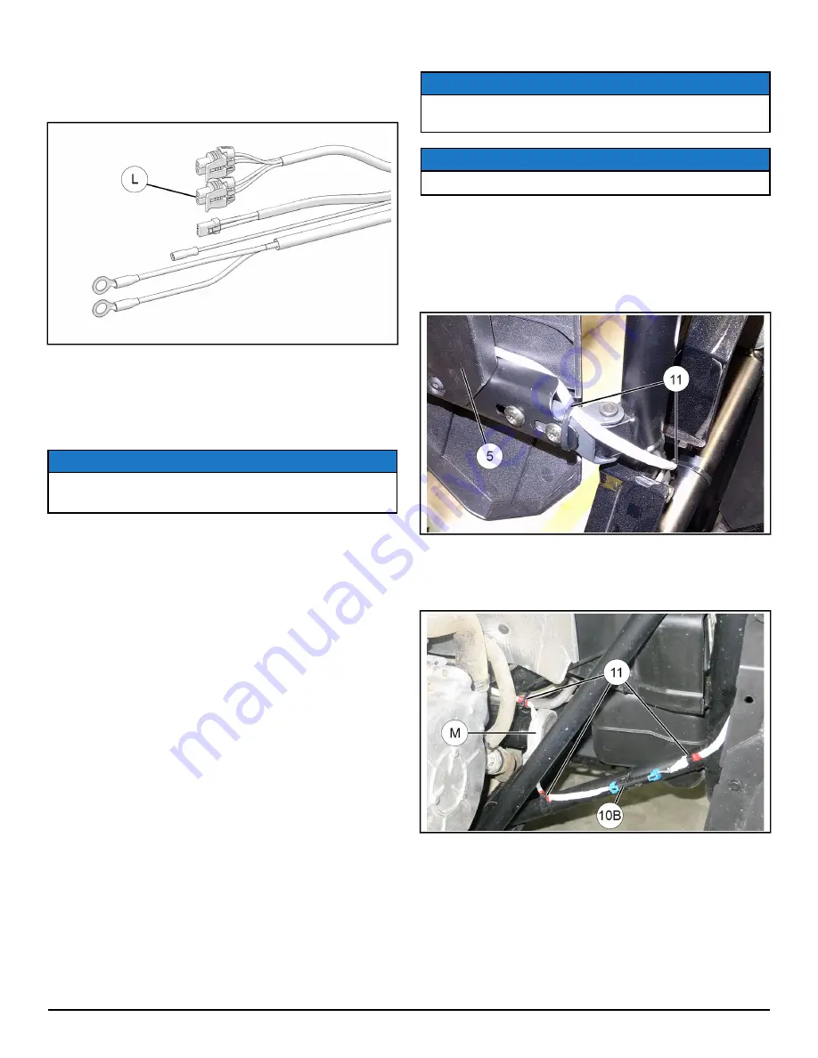
a. Route wires from RIGHT REAR speaker

assembly

t

to vehicle interior, then downward

into wheel well between vehicle frame and
body panel. Ensure adequate wire slack exists
(with door fully open), then secure wires to
door and vehicle frame using two cable ties

s

.

b. Join speaker wires to connector 10B on GRAY

wire speaker harness

a

, then secure to

vehicle frame using one cable tie

s

on each

side of connector.

c. Route GRAY wire speaker harness

a

forward

above engine mount

M

, then inboard towards

vehicle centerline. Secure harness to existing
vehicle routing clamp near engine mount using
one cable tie

s

as shown in previous step.

Summary of Contents for 2883116

Page 1: ...ains parts for installation of the REAR door panel speakers only Prior installation of the following additional kits is also required sold separately Amplifier Kit PN 2882122 Front Door Panel Speaker Kit PN 2881989 This Kit includes REF QTY PART DESCRIPTION PART NUMBER 1 1 Speaker Assembly LH includes items 2 4 2636792 2 1 Speaker Woofer 4016257 3 1 Crossover 4016382 4 1 Speaker Tweeter 4016381 In...

Page 2: ...s not shown 11 25 Cable Tie not shown 1 Instructions 9928521 TOOLS REQUIRED Safety Glasses Pliers Push Pin Rivet Pliers Side Cutting Screwdriver Set Torx IMPORTANT Your Rear Door Panel Speaker Kit is exclusively designed for your vehicle Please read the installation instructions thoroughly before beginning Installation is easier if the vehicle is clean and free of debris For your safety and to ens...

Page 3: ... sold separately See Step 5 for detail 9B Connector Speaker Front 2 female Door Panel Speaker Kit PN 2881989 and bundle kits 2882246 2882208 or equivalent kits sold separately See Step 5 for detail 9C Connector Speaker Rear 2 female Speaker harness a connector 10A Connectors 9B and 9C are electrically and physically identical The same signal is sent to front and rear speakers SPEAKER HARNESSES a a...

Page 4: ...dash panel then carefully pull panel rearward disengaging seven retaining clips B Retain screws If necessary for access label and disconnect other electrical harnesses from control panel f Remove center floor console i Remove five push pin rivets C and four screws D from front floor console Remove console pushing boots for gear shift and seat belt through console openings Retain rivets and screws ...

Page 5: ... and b for RH speaker assembly t 5 Install splitter harnesses NOTE See previous section HARNESS DETAIL for connector identification This step splits the left and right signals from the amplifier into left front left rear and right front right rear Connections will be WHITE to WHITE and GRAY to GRAY LEFT SIDE a Disconnect existing LEFT front speaker harness WHITE wires from corresponding amplifier ...

Page 6: ...IL for connector identification NOTE RH side shown LH side opposite a Route wires from RIGHT REAR speaker assembly t to vehicle interior then downward into wheel well between vehicle frame and body panel Ensure adequate wire slack exists with door fully open then secure wires to door and vehicle frame using two cable ties s b Join speaker wires to connector 10B on GRAY wire speaker harness a then ...

Page 7: ...looking forward and inboard from right rear wheel well second view looking rearward and downward through engine access panel e Repeat Steps a through d for LH speaker assembly q and WHITE wire speaker harness a f Route both white and gray speaker harnesses a forward through center console following battery cables then up into upper dash compartment to amplifier Secure speaker harnesses to battery ...

Page 8: ...il and secure excess harness length in upper dash compartment using cable ties s to prevent contact with hot components sharp edges or moving parts 7 Reconnect black negative cable to battery and reinstall seat 8 Restore access FEEDBACK FORM A feedback form has been created for the installer to provide any comments questions or concerns about the installation instructions The form is viewable on m...

Reviews: