background image

24

SAFETY

Safety Decals and Locations

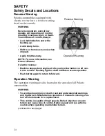
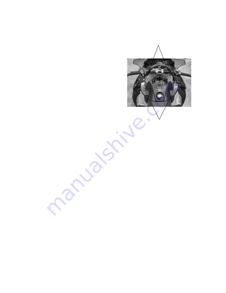
Reverse Warning

Polaris snowmobiles equipped with 

electric reverse have a reverse warning 

decal on the console.

WARNING
Reverse operation, even at low 

speeds, can cause loss of control 

resulting in serious injury or death. 

To avoid loss of control, always:

• Look behind before and while 

backing up.

• Avoid sharp turns.
• Shift to or from reverse only when 

stopped.

• Apply throttle slowly.

NOTE: For more information, see 

Owner's Manual.
If electric reverse:

• Machine stopped and engine at idle, push yellow button on LH con-

trol to reverse. Flashing light on dash indicates reverse operation.

• Push button again to return to forward.

Operation Warning

The operation warning decal is located on the console of all Polaris 

snowmobiles.

WARNING

• To avoid serious injury or death, read and understand all warnings 

and the Owner’s Manual before operation. If manual is missing, con-

tact a Polaris dealer for a replacement.

• This vehicle is capable of high speeds. Buried objects or uneven 

terrain can cause loss of control. Reduce speed and use extreme 

caution when operating in unfamiliar terrain.

(continued on next page)

Reverse Warning

Operation Warning

Summary of Contents for 700 Dragon RMK

Page 1: ......

Page 2: ......

Page 3: ...ons in this manual and on all product labels Failure to follow the safety precautions could result in serious injury or death WARNING The engine exhaust from this product contains chemicals known to the State of California to cause cancer birth defects or other reproductive harm ...

Page 4: ...r safe and enjoyable operation of your vehicle be sure to follow the instructions and recommendations in this owner s manual Your manual contains instructions for minor maintenance but information about major repairs is outlined in the Polaris Service Manual and should be performed only by a Factory Certified Master Service Dealer MSD Technician Your Polaris dealer knows your vehicle best and is i...

Page 5: ...f production components some minor discrep ancies may result between the actual vehicle and the information presented in this publi cation Depictions and or procedures in this publication are intended for reference use only No liability can be accepted for omissions or inaccuracies Any reprinting or reuse of the depictions and or procedures contained within whether whole or in part is expressly pr...

Page 6: ... of your snowmobile s controls and features The Perfect Fit 39 This section explains how to tailor the suspension and other features for an optimum riding experience Pre Ride Inspections 49 This section explains procedures that must be performed before riding Operation 56 This section explains proper engine break in operation of features and general operating procedures Maintenance 69 This section...

Page 7: ...4 ...

Page 8: ... are inspected by your dealer at specific mileage intervals You and your dealer must complete the registration form included with your snowmobile and forward it to us This completed form is necessary to ensure warranty coverage Protect and preserve your right to ride by joining your local trail riding clubs When teaching inexperienced operators to ride set up a predetermined course for practice Ma...

Page 9: ...of our environment Noise Level One of the most publicized issues about snowmobiles is noise The Society of Automotive Engineers SAE the standard setting body for snowmobile development recommends that snowmobiles conform to prescribed sound levels Polaris snowmobiles are engineered to conform to these SAE standards Our muffler systems are designed to reduce noise levels and must not be altered or ...

Page 10: ...ey can be duplicated only by ordering a Polaris key blank using your key num ber and mating it with one of your existing keys The ignition switch must be replaced if all keys are lost Vehicle Model Number ___________________________________________________ Tunnel VIN _____________________________________________________________ lower right side of the tunnel Engine Serial Number on valve cover ___...

Page 11: ...rt symbol on your vehicle or in this manual alerts you to the potential for injury WARNING The safety alert warning indicates a potential hazard that may result in serious injury or death CAUTION The safety alert caution indicates a potential hazard that may result in minor injury or damage to the vehicle CAUTION A caution indicates a situation that may result in damage to the vehicle NOTE A note ...

Page 12: ... snowmobile is in excellent operating condition at all times Always check major and vital safety components before every ride All Polaris snowmobiles are designed and tested to provide safe operation when used as directed Failure of critical machine components may result from operation with any modifications especially those that increase speed or power DO NOT MODIFY YOUR MACHINE The snowmobile ma...

Page 13: ...ck its operation WARNING Serious injuries may result if hands feet or clothing become entangled in the track Be alert when riding and remain properly seated to stay clear of the track Never hold the snowmobile up or stand behind it while warming up the track A loose track or flying debris could cause serious injury or death We recommend having your dealer perform all track service and alignment pr...

Page 14: ... must travel into remote areas always carry survival equipment that s appropriate to the condi tions you may encounter Such equipment may include but is not lim ited to extra clothing a sleeping bag a flashlight food and water a signaling mirror a means of building a fire and a two way radio or cel lular telephone Always carry the owner s manual on your snowmobile For added pro tection purchase an...

Page 15: ... will also be displayed on the label Eye Protection Do not depend on eyeglasses or sunglasses for eye protection When ever riding a Polaris vehicle always wear shatterproof goggles or use a shatterproof helmet face shield Polaris recommends wearing approved Personal Protective Equipment PPE bearing markings such as VESC 8 V 8 Z87 1 or CE Make sure protective eye wear is kept clean Clothing Be prep...

Page 16: ...snowmobile will travel about 120 feet 36 m If your speed is 60 MPH 96 km h your snowmobile will travel about 180 feet 55 m in two seconds Traveling at night requires extra caution Check headlight and taillight to ensure proper operation and don t over drive your headlight beam Always be able to bring your snowmobile to a stop in the distance illu minated by the headlight WARNING Operators with cog...

Page 17: ...o difficult to distinguish Make sure the way is clear before crossing railroads and other roads and highways The noise of your snowmobile will drown out the sound of approaching vehicles Look ahead behind and to both sides before turning or crossing railroad tracks or highways Steep embankments may also hide your view Always leave yourself a way out Variances in snow depth and or water currents ma...

Page 18: ...snow is connected You may be riding on a flat slope or snow covered road but if the snowpack above is unstable enough you can trigger an avalanche on a steeper slope above you Always be aware of snow conditions above you as you travel in mountainous terrain Before riding in mountainous terrain call or log on to your local ava lanche advisory to get current weather and snow stability information Fo...

Page 19: ...e clutch engaged allowing the engine s compression to help slow the snowmobile and keep it from rolling freely downhill WARNING Ice and snow build up may interfere with the steering of your snowmobile resulting in serious injury or death Keep the underhood area free of snow and ice WARNING When driving on long downhill stretches pump the brakes Riding the brakes may cause the brake system to overh...

Page 20: ...revent it from rolling back down the hill Stop the engine and set the parking brake if equipped Keeping away from the downhill side of the snowmobile pull the rear of the snowmobile around and point the front end and skis downhill Remount the snowmo bile restart the engine release the parking brake and descend the hill carefully WARNING Never attempt an abrupt change of direction when operating on...

Page 21: ...eeds Each clutch is dynami cally balanced before installation Any tampering may disrupt this preci sion balancing and create an unstable condition Cold Weather Drive Away Whenever your snowmobile has been parked for a length of time espe cially overnight always make sure the skis and track are loosened from ice and snow before attempting to drive Apply the throttle with enough authority to put the...

Page 22: ...ow then step down the snow in front of the snowmobile so that when the throttle is opened the snowmobile will be able to climb up and over the snow WARNING Do not drive for prolonged periods on blacktop gravel or ice Doing so could cause irreversible track damage and lead to serious injury CAUTION When operating on icy surfaces or hard packed snow avoid overheating the slide rail and track Lack of...

Page 23: ...ator s certificate For their pro tection as well as yours make sure they take a snowmobile safety course Everyone can benefit from the course Don t jump your snowmobile Jumping may injure your back because of spinal compression The seat and suspension of your snowmobile have been designed to provide protection under normal riding conditions Your snowmobile is not intended for this kind of use Be c...

Page 24: ...6 93 50 26 19 12 4 3 10 17 24 31 38 45 52 60 67 74 81 88 95 55 25 18 11 4 3 11 18 25 32 39 46 54 61 68 75 82 89 97 60 25 17 10 3 4 11 19 26 33 40 48 55 62 69 76 84 91 98 Frostbite in 30 min 10 min 5 min Wind Speed in KPH Actual Thermometer Reading _C 5 2 1 4 7 10 13 16 19 22 25 28 31 34 37 40 43 46 Equivalent Temperature _C Calm 5 2 1 4 7 10 13 16 19 22 25 28 31 34 37 40 43 46 8 3 0 7 11 14 18 22 ...

Page 25: ...t safety decals are provided by Polaris at no charge The part number is printed on the decal Clutch Cover Warning The clutch cover warning decal is under the hood on the clutch cover WARNING Do not operate engine with hood open Do not attempt adjustment with engine running Do not operate engine with ple num belt guard removed Never run engine with drive belt removed Never service clutches yourself...

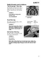
Page 26: ...RNING Stay clear of track Do not sit on seat back Entanglement with the track or a fall from seat back may result in severe injury or death Hot Surface Warning The hot surface warning is on the rear center of the tunnel WARNING Hot Surface Do Not Touch Burns may result Entire top of tunnel may be hot Install only accessories specifically approved for this model by Polaris Do not place clothing bag...

Page 27: ... Machine stopped and engine at idle push yellow button on LH con trol to reverse Flashing light on dash indicates reverse operation Push button again to return to forward Operation Warning The operation warning decal is located on the console of all Polaris snowmobiles WARNING To avoid serious injury or death read and understand all warnings and the Owner s Manual before operation If manual is mis...

Page 28: ...nger on approved models only reduce speed and allow extra space for steering and stopping A passenger reduces your ability to control the vehicle When operating on hard packed snow ice or when crossing roads steering and braking ability are greatly reduced Reduce speed and allow extra space to turn or stop To maintain vehicle control on ice or hard packed surfaces you should have a proper balance ...

Page 29: ... Headlight 4 Windshield 5 Mountain Bar if equipped 6 Handlebar 7 Seat 8 Taillights 9 Rear Bumper 10 Snow Flap 11 Track 12 Tool Storage 600 13 Suspension 14 Tunnel 15 Side Panel 16 Ski 17 Nosepan 1 2 17 11 12 10 9 16 6 5 4 3 7 8 13 14 15 ...

Page 30: ...y 4 Engine Stop Switch 5 Throttle Control 6 Recoil Starter Handle 7 Hood Hold Down Straps 8 Brake Lever 9 Parking Brake 10 Handlebar Grip Warmer Switch 11 Thumbwarmer Switch 12 Electronic Reverse Button 13 MFD Control 14 Headlight Dimmer Switch 1 2 8 3 4 5 7 6 14 9 10 11 12 13 ...

Page 31: ...stem allows you to adjust the handlebar posi tion to fit your style of riding See page 47 Adjustable Headlights Move the adjuster to the left to lower the headlight beam Move the adjuster to the right to raise the headlight beam Fuel Valve 600 RMK The fuel valve is located under the hood Turn the fuel valve off when ever the snowmobile is stored or parked 1 Turn the valve clockwise to turn off the...

Page 32: ...s detonation beyond a preset limit it retards ignition timing and adds fuel to reduce the detonation and prevent engine damage When the detonation returns to a permissible level the system will return spark and fuel to normal allowing the engine to run at rated power levels Sensor Fail Safe The DET includes a sensor fail safe system to prevent the engine from damage if the sensor fails becomes dis...

Page 33: ...tion MFD Component Identification Item 1 Analog Gauge if equipped 2 Digital Gauge 3 Check Engine Indicator 4 Low Oil Indicator 5 High Temp Indicator 6 Brake Indicator 7 Reverse Indicator 8 High Beam Indicator 1 2 3 5 6 7 8 4 ...

Page 34: ...rval 2 Electrical System Voltage Level 3 MAX Maximum MPH KPH or RPM MPH Miles per hour KPH Kilometers per hour RPM Engine crankshaft revolutions per minute 4 Air Temp if equipped Engine Temp Degrees Celsius Degrees Fahrenheit 5 Miles Kilometers 6 Hours Trip 1 Trip 2 Trip F Service Label Altitude Label 1 2 3 4 5 6 ...

Page 35: ...ther standard or metric units of measurement While viewing a screen that displays measurements MPH km h or temperatures press and hold the MODE switch until the unit of mea surement changes about 10 seconds Speedometer Tachometer To change viewing preferences press and hold the MODE button for three seconds When the button is released the new setting becomes active and screen colors change Option ...

Page 36: ...see page 32 Press and release the SET button to cycle through the following screens odometer trip 1 odometer trip 2 odometer fuel trip odometer if fuel is low and clock if equipped Use the following procedures to make changes to these screens Odometer Setting The odometer records the vehicle s total distance traveled since manufacture The odometer cannot be reset Trip Settings Trip 1 and Trip 2 ar...

Page 37: ...et to zero after refueling Engine Program Press and release the MODE button until the engine program screen is active The default display for this screen includes engine hours electri cal system voltage level fuel level if equipped and either engine cool ant temperature air temperature accessory or altimeter accessory Press and release the SET button to cycle through the following screens hour met...

Page 38: ...gits begin to flash release the SET button 5 Press and release the SET button to advance the reading in 50 foot 15 m increments or press and hold the button to advance quickly Adjust the altitude display to within 50 ft 15 m of the current alti tude NOTE The gauge reads barometric pressure and allows the rider to compen sate for daily fluctuations in air pressure The gauge can adjust the displayed...

Page 39: ...Speed Maximum RPM The gauge automatically logs the maximum speed and engine RPM even if the history program is not active in the display 1 Enter the History Program 2 Press and release the SET button until one of the two screens is active NOTE The MPH and RPM values are both reset at the same time Reset the val ues before each run to obtain accurate readings 3 Press and hold the SET button for thr...

Page 40: ...m 2 Press and release the SET button until the service interval screen is active 3 Press and hold the SET button for ten seconds continuing to hold even after the display begins to flash 4 When the display stops flashing release the button The service interval has been reset To reset the reminder at a new interval 1 Enter the History Program 2 Press and release the SET button until the service int...

Page 41: ...loth and a mild soap and water solution Do not remove the electrical connectors or pro tective rubber boot Do not spray the back side of the gauge or the wire harness with a pressure washer or other water source CAUTION To prevent damage to the lens do not use alcohol for cleaning Do not allow chemicals or sprays to contact the lens Immediately clean off any gasoline that splashes on the gauge dur...

Page 42: ...ry settings and then customizing each adjustment individually to suit rider preference The snowmobile should be methodically tested one change at a time under the same conditions trail and snow condi tions vehicle speed riding position etc after each adjustment until the best ride is achieved IFS Components 1 Ski 2 Front shock and spring 3 Rod ends 4 Upper control arms 5 Lower control arms IFS Adj...

Page 43: ...sing full travel push the jounce bumper down on the shock rod until it contacts the body and test ride the machine The bumper will move up on the rod in relation to the amount of travel that was used dur ing the ride If the travel is full the bumper will be seated at the top of the rod Shock Absorber Components 1 Retainer 2 Jounce Bumper 3 Shock Rod 4 Body 5 Threaded Spring Preload Adjuster Nut 6 ...

Page 44: ...the spring preload too much may adversely affect the han dling of the snowmobile and the per formance of the suspension Never exceed one inch of preload beyond the factory settings and ensure that both sides are adjusted the same When decreasing preload make sure at least two turns of preload are hold ing the spring between the retainer on top of the shock and the threaded spring preload adjuster ...

Page 45: ...n evaluate the change For further assistance see your dealer Suspension Performance Tips Rider weight usually determines the position at which the spring pre load should be set However this may vary with riding style With a little experimentation each rider can find a preferred set up These adjustments are easy to make involve very little time or effort and greatly affect the ride In deep snow a n...

Page 46: ...the distance between the ground and the rear bumper at the exact location used for measure ment X This is measurement Y To determine sag commonly referred to as ride in subtract measure ment Y from X Sag X Y Adjust sag by rotating the torsion spring preload cams located on the rear torque arm See illustration The ideal amount of sag for this rear suspension is five inches 12 7 cm X Y 5 in 12 7 cm ...

Page 47: ...ed only as a guideline to be used for initial suspension set up Your set up may vary based on your desired riding style Soft long end of cam to front Medium short end of cam up Firm long end of cam up Limiter Strap Position The following information is pro vided only as a guideline to be used for initial suspension set up Your set up may vary based on your desired riding style High Limiter strap i...

Page 48: ... base of the shock In half turn increments turn the screw clockwise to increase compres sion valving and stiffen the ride Turn the screw counterclockwise to reduce compression and soften the ride There are approximately three full turns of adjustment available If bottoming continues after the screw has been turned fully clockwise the torsion spring should be adjusted see page 44 Return the screw t...

Page 49: ...bars are turned fully to the left or right When adjustments are complete torque the front adjuster block bolts first then torque the rear bolts Torque the bolts to 11 13 ft lbs 15 18 Nm WARNING Some aftermarket accessories including windshields and cargo bags may interfere with the handlebar Such accessories could limit your ability to steer the vehicle and or may contact the brake lever This coul...

Page 50: ...t the handlebar forward or rearward to the desired position 3 Tighten the bolts Handlebar Angle 1 Loosen the four bolts on the top of the adjuster block NOTE If necessary pry the blocks apart with a screwdriver 2 Adjust the handlebar forward or rearward to the desired angle 3 Tighten the bolts Loosen top bolts to adjust handlebar angle Loosen bottom bolts to adjust handlebar position ...

Page 51: ...may result in Non compliance with government industry requirements Voiding of warranty Injury to self or others This applies but is not limited to the following areas brakes clutches fuel systems and exhaust systems NOTE Exhaust systems are critical safety areas that must use approved Polaris parts Please see your Polaris dealer for service Tether Switch The accessory tether switch is available fo...

Page 52: ...pe 51 Parking Brake Lock Brake Lever Brake System 51 52 91 Throttle Lever 50 Throttle Safety Switch 50 Auxiliary Shut Off Switch Engine Stop Switch 55 65 Ignition Switch 55 65 Taillight Brakelight Headlight 55 Coolant Level 86 Gearcase Oil Level N A Engine Oil Level 77 Suspension Mounting Bolts 54 Skags Wear Bars 107 Ski Saddle and Spindle Bolts 54 Hood Straps Latches 50 Seat Latches if equipped N...

Page 53: ...moothly or if you discover excessive lever freeplay DO NOT start the engine Have the throttle serviced immediately n Throttle Safety Switch Test the throttle safety switch system before the snowmobile is operated See page 63 for procedure n Hood Latches The hood of the snowmobile protects the operator from moving parts as well as aiding in sound emission control and other functions Under no circum...

Page 54: ...ser to the handgrip than 1 2 1 3 cm A smaller distance indicates low brake fluid level or air in the hydraulic system Refer to the brake bleeding infor mation on page 94 Brake Lever Feel If the brake lever feels spongy when squeezed check the brake fluid level and condition Add fluid as needed See page 93 Check for the presence of air in the fluid system See page 94 for more information or see you...

Page 55: ...into place Do not force the lock or it may break The parking brake light on the gauge will light up if the parking brake lever lock is set while the engine is running It will also be lit when the service brake is in use If the parking brake light does not come on when the parking brake or service brake is in use have it serviced by your dealer Lock Release To release the lock squeeze the brake lev...

Page 56: ...ailure caused by operation on ice or poor lubrication conditions voids the track warranty Deep Lug Tracks if equipped The 2 4 powder track is designed specifically for deep snow applica tions Operation in low snow conditions at high speeds may cause track lug separation Track lug separation is not covered under the Polaris limited warranty policy Polaris does not recommend operation above 70 mph w...

Page 57: ...ck the follow ing items on a weekly basis or before any long trip Item Check Page Suspension mounting bolts Tightness Rear idler wheel bolts Tightness 103 Rear idler adjusting bolt locknuts Tightness Torque arm bolts Tightness Carrier and bogie wheel bolts Tightness Front torque arm limiter strap Condition Rail slide Condition 108 Track Tension 102 All rear suspension components Lubrication 75 Ski...

Page 58: ...F n Tether Switch If your machine has a tether switch remove the tether from the switch to make sure the engine stops immediately n Lighting Check the headlight high and low beam taillight and brake light Replace burned out lamps before operating n Mirror Adjustment If equipped adjust your mirrors so they can be used to their full advan tage n Operating Area Before driving away check your surround...

Page 59: ...n when the engine starts If not equipped with electric start grasp the starter handle and pull slowly until the recoil engages then pull abruptly to crank the engine 5 Repeat the cranking procedure as needed until the engine starts NOTE It may require as many as eight to ten pulls to prime the fuel system and start the engine if the fuel tank has been completely emptied WARNING Before starting the...

Page 60: ... three hours of operation will damage close fitted engine parts Do not operate at full throttle or high speeds for extended periods during the first three hours of use Vary the throttle open ings and machine speeds to reduce friction on all close fitting machined parts allowing them to break in slowly without damage Use of any lubricants other than those recommended by Polaris may cause serious en...

Page 61: ... also be incompatible and the result could be sludge formation filter blockage and reduced cold weather flow rates All Polaris oils are compatible with each other Slide Rail and Track Cooling CAUTION Serious engine damage can occur without the proper lubrication Check the oil tank level often during the first tank of fuel If the oil level doesn t go down contact your dealer immediately CAUTION Ina...

Page 62: ... shut off the engine and lower the snowmobile to the ground 5 Grasp the skis by their front loops and move them from side to side to loosen snow and ice WARNING A loose track or flying debris could cause serious injury or death Stand clear of the front of the machine and the moving track Never hold the snowmobile up or stand behind it while warming up the track Do not use excessive throt tle durin...

Page 63: ...es or sparks in or near the area where refueling is performed or where gasoline is stored If gasoline spills on your skin or clothing immediately wash it off with soap and water and change clothing Never start the engine or let it run in an enclosed area Engine exhaust fumes are poisonous and can cause loss of consciousness or death in a short time WARNING The engine exhaust from this product cont...

Page 64: ...uel system icing and lean fuel mixtures Never use deicers or additives containing methanol Polaris also recommends the use of Carbon Clean Plus See page 112 for the part numbers of Polaris products If you use oxygenated fuel containing ethanol additional alcohol deic ers or water absorbing additives should not be used CAUTION Operating with obstructed fuel systems will result in serious engine dam...

Page 65: ...result in engine damage This is especially important when the machine is operated in mountainous ter rain Maintain the oil level at the bottom of the filler neck Always check and fill the oil tank when refueling Never operate the engine if oil is not vis ible in the tank NOTE The Polaris oil cap on the oil bottle is vented to allow proper oil flow See your Polaris dealer for recommended replacemen...

Page 66: ...peration 1 Sit on the seat 2 Start the engine and allow it to idle 3 Hold the throttle lever pin stationary by exerting pressure on the pivot pin in the direction shown in the illustration 4 Apply a slight amount of throttle A properly functioning switch must shut down the engine WARNING Operating the snowmobile with a faulty throttle safety switch can result in serious injury or death in the even...

Page 67: ...n the throttle cable may cause the safety switch to activate preventing the engine from starting If this occurs return the snowmobile to an authorized Polaris dealer for service If an emergency exists and it s necessary to start the engine the throttle safety switch and engine stop switch may be disconnected from the wire harness When these switches are disconnected the ignition key switch must be...

Page 68: ...about the engine stop switch SYSTEM WHAT IT DOES THROTTLE CONDITION Ignition Switch Interrupts ignition circuit All Brake Slows jackshaft All Engine Stop Switch Interrupts ignition circuit All Choke if equipped Floods engine Half throttle or less Throttle Safety Switch Interrupts ignition circuit All Tether Switch if equipped Interrupts ignition circuit All ...

Page 69: ...counterclockwise around the clutch as shown 5 Pull the strap abruptly so the strap comes free of the clutch while starting the engine Repeat until the engine starts 6 Reinstall the air box and side panel 7 Close and secure the hood WARNING Serious injury can result from wrapping the start strap around your hand while using the emergency starting procedure DO NOT wrap the start strap around your ha...

Page 70: ...ngine stops running the snowmobile will be in forward gear when it s restarted Disengaging Reverse 1 Stop the snowmobile and leave the engine idling 2 Push the yellow reverse button for one second and release The engine will slow and begin to rotate forward The light on the instrument panel will shut off 3 Apply the throttle slowly to make sure the snowmobile is in for ward WARNING Improper revers...

Page 71: ...with a rope have no braking power and can easily collide with the rear of the snowmobile or other objects resulting in serious injury or death DO NOT tow toboggans sleds saucers or any type of vehicle with a rope Only a stiff metal pole connecting the towed object and the tow hitch on the snowmobile should be used If passengers are to be towed on a tobog gan or sled make sure the pole is at least ...

Page 72: ...l should not be removed even after you purchase the snowmobile You may remove the factory installed emissions information hangtag which is intended solely for your use in making a purchasing decision Emission Control Maintenance Requirements Your snowmobile is certified to operate on gasoline with a minimum octane level of 87 R M 2 The emission control system designation per SAE J1930 is EM If you...

Page 73: ...the manual You must inspect the air intake system on your snowmobile prior to each use including the airbox foam filter and hood foam filters and clean these components as necessary Polaris considers the specified maintenance for the spark plugs oil changes air intake system and exhaust valves to be critical emission related maintenance The speci fied maintenance for the fuel filter is recommended...

Page 74: ...ervals All necessary replacement parts and labor incurred with the exception of authorized warranty repairs become the responsibility of the regis tered owner If during the course of the warranty period part failures occur as a result of owner neglect in performing recommended regular maintenance the cost of repairs are the responsibility of the owner Personal safety is critical when attempting to...

Page 75: ...00 km 1000 mi 1600 km 2000 mi 3200 km Pre Season CLUTCH Clutch Alignment Offset without belt 96 I I I Drive Belt Condition 97 I I I I Clutches disassemble 96 C C C Belt Tension I I I I Clutch Sheaves 96 I I I I ENGINE COOLING Engine Mounts I I I I Recoil Rope I I I I Engine Torque Stop 99 I I I I Cylinder Head Bolts I I I Cylinder Base Nuts I I I I Ignition Timing BTDC I I I VES System C C C I Coo...

Page 76: ...arburetor 600 synchronize 83 I I I Idle RPM I I I Throttle Lever 50 64 I I I I I Oil Pump Lever synchronize I I I Throttle Cable 76 L L L Choke Cable 600 76 L L L Choke 600 76 I I I Vent Lines I I I I Throttle Position Sensor I I I Fuel Lines 82 I I I I I Fuel Filter 82 R R Oil Filter 82 R R Oil Lines 82 I I I Air Box Plenum I I I I I Fuel Injectors 700 I I I Drain Water Traps 600 84 I I I ELECTRI...

Page 77: ... for service at 1500 mi 2000 km Suspension Shock Oil I I I I Cooling Fins and Shroud I I I I Drive Shaft Bearings 76 L L L I Jackshaft Bearings 109 L L L I Skags Wear Bars 107 I I I I I Ski Saddle Spindle Bolts I I I I I Drive Chain Tension 90 I I I I I Hood Latches 50 I I I I I Rear Wheel Idler Bolts 103 I I I I I Idler Bolt Jam Nut 103 I I I I I Rear Suspension Pivot Shafts 75 L L L Camber Align...

Page 78: ...Season Grease at the intervals outlined in the Periodic Maintenance Table beginning on page 72 and before seasonal storage When operating in heavy wet snow conditions lubricate every 500 miles 800 km Lack of lubrication will adversely affect your ride and the life of the sus pension For more information about suspension lubrication and adjust ments see your Polaris dealer ...

Page 79: ...than four pumps Throttle Cable Lubricate the throttle cable lightly with grease or oil With the engine off turn the handlebars to the left and lubricate liberally as shown Choke and Choke Cable Lubricate the choke slide and cables lightly with oil or grease Before turning the engine off operate the choke intermittently to draw moisture out of the choke plunger area and reduce the possi bility of t...

Page 80: ...nge the chaincase oil after the first 500 miles 800 km then every 1000 miles 1600 km or seasonally Polaris recommends the use of Polaris Synthetic Chaincase Lube See page 112 for the part numbers of Polaris products Oil Check 1 Position the vehicle on a level sur face 2 View the oil level at the sight glass 3 Remove the fill plug and add the recommended oil as needed Do not overfill 4 Reinstall th...

Page 81: ... the plug 4 Install a new sealing washer on the drain plug NOTE The sealing surfaces on the drain plug and the oil tank should be clean and free of burrs nicks or scratches 5 Reinstall the drain plug Torque to 6 10 ft lbs 8 13 Nm 6 Remove the fill plug Clean off all metal shavings from the plug 7 Add 11 oz 325 ml of the recommended oil Do not overfill 8 Reinstall the fill plug making sure it is se...

Page 82: ...tan or light brown There will be few combustion deposits The electrodes are not burned or eroded This indi cates the proper type and heat range for the engine and the service NOTE The tip should not be white A white insulator tip indicates overheating caused by use of an improper spark plug or incorrect carburetor throt tle body adjustments Wet Fouled Spark Plug The wet fouled insulator tip is bla...

Page 83: ... spark plugs Spark Plug Removal and Replacement 1 Remove the spark plug cap 2 Using the special wrench provided in the tool pouch rotate the spark plug counterclockwise to remove it 3 Reverse the procedure for spark plug installation 4 Torque to specification 5 Reinstall the spark plug cap CAUTION Using non recommended spark plugs can result in serious engine damage A spark plug with a heat range ...

Page 84: ...w check the top of the foam filter periodically to remove any accumulation of snow CAUTION Operating the 600 RMK with the intake filters removed may cause carburetor icing The result will be poor fuel economy or carburetor malfunction Always reinstall the intake filters before operating the snowmobile Intake Foam Filters Pre filter ...

Page 85: ...ion or damage Always check fuel line condition after periods of storage Normal dete rioration from weather and fuel compounds may occur Replace worn or damaged fuel lines promptly Oil Lines Inspect oil line condition at the intervals outlined in the Periodic Main tenance Table beginning on page 72 Oil Filter Have your dealer change the oil filter and bleed the system at the intervals outlined in t...

Page 86: ...chronized or balanced is important Properly adjusted carburetors can greatly improve engine performance fuel economy engine life and reliability If you notice any of the following conditions the carburetor may need adjustment Hard starting Poor idle Overheated pistons and cylinder walls Plug fouling Poor engine response to various throttle valve openings CAUTION Operating the snowmobile with incor...

Page 87: ...ntainer or shop towels below the plug to catch drained fuel 3 Slide the clamp away from the drain plug and remove the drain plug from the sedi ment tube 4 Wipe residue from the plug and reinstall it Reposition and tighten the clamp 5 Repeat the draining proce dure for any remaining traps WARNING When draining the traps fuel spillage will occur Always work in a well venti lated area away from anyth...

Page 88: ...system to cool completely before inspecting 1 Open the hood and inspect the muffler and pipes for cracks or dam age 2 Check for weak or missing retaining springs or damper support grommets 3 Check for loose clamps on the pipe covers WARNING Hot exhaust system parts can cause serious burns Allow adequate time for the exhaust system to cool Never perform this procedure with the engine running ...

Page 89: ...ever add tap water to the cooling system Minerals cause deposits and may react adversely with the metals in the engine and cooling system n Coolant Level The engine coolant level is controlled by the recovery system The recovery system components are Coolant bottle or overflow tank Filler neck Pressure cap Connecting hoses Always maintain the coolant level between the minimum and maximum marks on ...

Page 90: ...n Driving in deep snow will also help cool the engine See your dealer for service Add coolant if the level is low NOTE Engine performance will be reduced if you continue operating when the high temperature light is on Flushing the Cooling System To ensure that the coolant maintains its ability to protect the engine drain the system completely every two years and add a fresh mixture of antifreeze a...

Page 91: ...ct your dealer for the correct part WARNING Steam and hot liquids will cause serious burns to your skin Never bleed the cooling system or remove the pressure cap when the engine is warm or hot CAUTION If coolant flow becomes restricted or plugged coolant loss air lock or engine damage may result Most cooling systems are equipped with a filter that should be periodically inspected or replaced ...

Page 92: ... thermostat housing Allow the coolant to bleed through the system until it runs out the bleed holes Reinstall the bleed screw into the manifold 4 Add coolant to the coolant bottle to the maximum mark 5 Start the engine and run at a fast idle for two to three minutes Loosen the bleed screw occasionally to purge any trapped air 6 Stop the engine and check the coolant bottle level Fill as required 7 ...

Page 93: ...ll chain slack to the tensioner side Lock the brake lever lock or have an assistant hold the brake lever firmly 2 Loosen the adjuster bolt jam nut 3 Finger tighten the adjuster bolt until it can no longer be adjusted by hand then back off 1 4 turn 4 Tighten the jam nut while holding the adjuster bolt Torque to 21 ft lbs 28 Nm 5 Release the brake lever lock Adjuster Bolt Jam Nut ...

Page 94: ...approximately 1 16 1 5mm A kit is avail able for replacing brake pads See your dealer WARNING Brake failure during operation can result in serious injury or death Properly functioning brakes are vital to your safety Be sure the brake pads do not drag on the disc and that brake lever travel is not excessive Always replace brake pads when the brake pad material becomes thinner than the backing plate...

Page 95: ...lace when thickness is less than 1 16 1 5mm Excessive Lever Travel Hydraulic brakes are self adjusting but if excessive brake pad clearance develops see page 91 bring the snow mobile to an authorized Polaris dealer for inspection and adjustment Brake Disc Bleed Screw Brake Pad Material Brake Line Brake Caliper ...

Page 96: ...luid always discard any unused portion Never store or use a partial bottle Brake fluid is hygroscopic meaning it rap idly absorbs moisture from the air The moisture causes the boiling tempera ture of the brake fluid to drop which can lead to early brake fade and the possibility of accident or serious injury WARNING Keep the master cylinder cover free of dirt and debris The vent slits allow for dia...

Page 97: ...valve and direct the flow of fluid into an approved container 4 Squeeze the brake lever a full stroke Then unscrew the bleeder valve 3 4 of a turn to release air 5 Close the bleeder valve and release the brake lever 6 Repeat steps 4 and 5 until fluid flows from the bleeder valve in a solid stream free of air bubbles 7 After bleeding is complete refill the reservoir to the proper level See page 93 ...

Page 98: ...hed to the bulb with draw the bulb from the housing 5 Grasp the bulb by its metal base and carefully separate the bulb from the harness Installing Halogen Bulbs 1 Hold the bulb by its metal base and install it into the wire harness 2 Insert the bulb into the housing 3 Connect the spring to the housing 4 Carefully flip the spring back into the housing placing it around the wire harness 5 Reinstall ...

Page 99: ...but can drastically change the shift pattern resulting in poor performance See your dealer for service and adjustments NOTE A worn belt will continue to function but will not deliver maximum performance Always carry a spare belt in case of an emergency WARNING If you become aware of higher than normal clutch engagement or an unusual vibration or shift pattern see your dealer immediately Do not ope...

Page 100: ...t Deflection Measure belt deflection with both clutches at rest and in their full neutral position Place a straight edge on the belt and apply downward pressure while measuring at point A This measurement should be 1 1 4 3 2 cm Drive Belt Adjustment TEAM Clutch 1 Install the L wrench into the open threaded hole in the outer sheave of the clutch see page 98 Turn the wrench clockwise slightly to rem...

Page 101: ...o a complete stop 3 Lock the parking brake 4 Open the hood 5 Remove the left side panel 6 Locate the L wrench in the tool kit Install the wrench into the open threaded access hole in the outer sheave of the clutch 7 Turn the wrench clockwise until the sheaves open far enough to remove the belt CAUTION Do not attempt to remove the drive belt after operating in reverse The snow mobile must be stoppe...

Page 102: ...e L wrench counter clockwise to tighten the sheaves while working the belt to the outer edge of the sheaves 3 Remove the wrench and store it in the tool kit 4 Reinstall the side panel 5 Close and secure the hood Torque Stop Periodically check torque stop clearance With clutches in proper align ment measure rear torque stop clearance from the engine case Rear torque stop clearance should be 010 030...

Page 103: ...the track along the entire length of each rod Bend the track to check for breakage 4 Replace the track if any rod dam age is found CAUTION Installing tracks with larger lugs on machines equipped with coolers will result in damage to the cooler or tunnel Always install a track having the lug size recommended for your model WARNING Broken track rods can cause a rotating track to come off the machine...

Page 104: ...the track warranty WARNING Operating with insufficient lubrication between the rail slide and track guide clips can cause track failure loss of vehicle control and loss of braking ability which can result in serious injury or death Avoid operating for extended periods on ice and other surfaces that have lit tle or no snow for lubrication CAUTION High speed use on hard packed surfaces is not recomm...

Page 105: ...ce see chart ahead of the center of the rear idler wheel NOTE Measure at the point where the weight is placed 4 Check for specified slack between the wear surface of the track clip and the plastic rail slide WARNING Moving parts can cut and crush body parts When performing the checks and adjustments recommended on the following pages stay clear of all moving parts Never perform track measurement o...

Page 106: ...eat the measurement on the other side of the track NOTE Check more frequently when the snowmobile is new 9 Start the engine and slowly rotate the track at least five revolutions Let the track come to a stop do not apply brakes 10 Check track alignment see page 104 and adjust as necessary 11 Tighten the lock nuts 12 Tighten the idler shaft bolts Torque to 35 ft lbs 47 5 Nm Idler Shaft Bolt Adjustin...

Page 107: ...e com plete revolutions Stop the engine and let the track come to a stop do not apply brakes 3 Inspect track alignment by looking through the track window to make sure the rails are evenly spaced on each side If the track runs to the left loosen the left locknut and tighten the left adjusting bolt If the track runs to the right loosen the right locknut and tighten the right adjusting bolt 4 After ...

Page 108: ...105 MAINTENANCE Steering System Steering Inspection and Adjustment Check all steering system fasteners weekly and before a long ride Tighten any loose fasteners ...

Page 109: ...the skis at point X should be 1 8 to 1 4 3 6 mm greater than the measurement at point Y NOTE If the skis are misaligned we recommend that your dealer correct the alignment since camber adjustment may also be affected WARNING Improper ski alignment or adjustment may cause loss of steering control resulting in serious injury or death Do not attempt to change the ski align ment or camber adjustment S...

Page 110: ...the snowmobile so the skis are approximately 6 15 cm from the ground 2 Remove the attaching nuts and pry the skag downward 3 Remove the front end of the skag 4 Remove the rear end of the skag 5 Reverse the steps to install a skag WARNING Worn skis and or skags will adversely affect handling Loss of vehicle control may result causing serious injury or death See your dealer s studding chart for reco...

Page 111: ...a wear limit indicator groove to indicate the minimum permissible slide thick ness Replace the rail slides if they are worn to the top of the groove at any point along their length Failure to do so may result in permanent damage to the track or rails Replace when worn to top of groove Minimum Thickness ...

Page 112: ...ion with waxes and rust inhibitors grease oil or paint The snowmobile should be stored in a dry garage or shed out of direct sunlight and covered with a fabric snowmobile cover Plastic tarp may cause condensation to form and damage snowmobile components Controls and Linkage Lubricate all bushings spindle shafts tie rod ends and cables as outlined in the Periodic Maintenance Table beginning on page...

Page 113: ...e water trap drain plugs See page 84 Jet restriction caused by improper storage can cause lean conditions and very poor slow speed driving quality Engine Protection DRAGON RMK Proper preparation of the engine and fuel system is vital to the preven tion of rust and corrosion on precision engine parts during storage Whenever the machine is stored for a period of more than 60 days the engine must be ...

Page 114: ...ension Moderate track tension should be maintained during summer storage The machine should be supported off the ground to allow the track to hang freely Transporting the Snowmobile Whenever the snowmobile is transported 1 Turn the fuel valve off See page 28 2 Be sure the fuel cap and oil cap are installed correctly 3 Always tie the snowmobile to the transporting unit securely using suitable strap...

Page 115: ...43 VES II Synthetic 2 Cycle Engine Oil 2 5 gal Chaincase Lubricants 2873105 Synthetic Chaincase Lubricant qt 2872951 Synthetic Chaincase Lubricant 12 oz Grease Specialized Lubricants 2871312 Grease Gun Kit Premium All Season 3 oz 2871322 Premium All Season Grease 3 oz cartridge 2871423 Premium All Season Grease 14 oz cartridge 2871329 Dielectric Grease Nyogelt Coolant 2871323 Anitfreeze 60 40 Prem...

Page 116: ... drive belt Excessive belt sheave clearance SEE YOUR DEALER Drive belt turns over Wrong belt for appli cation Replace the drive belt Clutch alignment out of spec SEE YOUR DEALER Engine mount bro ken or loose Inspect and replace SEE YOUR DEALER Machine fails to move Clutch jammed Check for twisted belt or broken spring SEE YOUR DEALER Track jammed Foreign object may be caught or the rail slide melt...

Page 117: ...ow RPM per formance Worn drive belt Inspect and replace as needed Excessive belt sheave clearance SEE YOUR DEALER Loose torque stop Inspect and adjust Sticky clutch SEE YOUR DEALER Poor fuel quality Use 87 91 octane fuel or higher Engine doesn t turn Seized engine SEE YOUR DEALER Seizure is a result of poor lubrication inade quate fuel supply broken parts or improper cooling Hydrostatic lock Fuel ...

Page 118: ...perating SEE YOUR DEALER Engine lacks power Fouled or defective spark plug s Replace the plug s Fuel filter loss of high RPM power SEE YOUR DEALER Incorrect clutching SEE YOUR DEALER Carburetor and fuel pump There is no adjustment to change power output SEE YOUR DEALER Engine continually backfires Faulty plug s Change plug s Carburetor Fuel System Dirt or ice may be in the fuel system deicer shoul...

Page 119: ...to achieve correct sag Move limiter strap to low position see page 44 Front end pushes Check for worn skags Check for binding front suspension shafts steering compo nents grease all pivot points elevate front of machine Set static sag see page 43 Adjust torsion spring blocks or install optional torsion springs to achieve correct sag Increase IFS preload if equipped see page 41 Move limiter strap t...

Page 120: ...atures Check for snow ingestion Ice and snow build up between track and tunnel Warm the engine at least five minutes Take the drive belt off the machine in extremely cold weather and warm it up Break machine loose from the snow Poor engine performance Check for carburetor and choke synchronization fouled plugs debris in the carburetor s and water ice or dirt in the fuel tank or fuel line Loading m...

Page 121: ... contained in this manual Your dealer is also familiar with Polaris policies and procedures and will be happy to assist you When contacting us about parts service or warranty always provide the following information 1 Serial number 2 Model number 3 Dealer name 4 Date of purchase 5 Details of trouble experienced 6 Length of time and conditions of operation 7 Previous correspondence Use the page pro...

Page 122: ...e owner reports theft A In addition to notifying the proper law enforcement officials the owner must call Polaris Customer Service B Owners must provide their name address telephone number and the model and serial number of stolen machines 2 Polaris warranty will provide all dealerships with a monthly updated list of all stolen units to further monitor thefts 3 Polaris warranty will aid in notifyi...

Page 123: ...s not caused by a defect in material or workmanship The warranty does not cover accidental damage normal wear and tear abuse or improper handling The warranty also does not cover any snowmobile that has been structurally altered neglected improperly maintained used for racing or used for pur poses other than for which it was manufactured The warranty does not cover any dam ages that occur during t...

Page 124: ...st present your copy of the Warranty Registration form to the dealer The cost of transportation to and from the dealer is YOUR responsibility Polaris recommends that you use your original selling dealer however you may use any Polaris Servicing Dealer to perform warranty service Please work with your dealer to resolve any warranty issues Your dealer will contact the appropriate personnel at Polari...

Page 125: ...overage in the event of a warranty claim This warranty also excludes failures resulting from improper lubrication improper engine timing improper fuel surface imperfections caused by external stress heat cold or contamination operator error or abuse improper component alignment tension adjustment or altitude compensation failure due to snow water dirt or other foreign substance ingestion contamina...

Page 126: ...Coverage is automatic with no addi tional paperwork required The free Second Year Engine Service Contract is subject to a 50 deductible per visit Regular documented service maintenance visits are required to validate this warranty A partial list of items excluded from coverage includes Damage due to accident fire explosion theft or other causes beyond Polaris control Damage caused by the failure o...

Page 127: ...take your vehicle to an authorized Polaris dealer You must show the dealer photo identification from the country of the selling dealer s authorized location as proof of residence Upon residence verification the servicing dealer will be authorized to per form the warranty repair If You Move If you move to another country be sure to contact Polaris Customer Assistance and the customs department of t...

Page 128: ...e covered by this warranty This includes compo nents whose failure increases the snowmobile engine s emissions To the extent they are present on your snowmobile engine this includes electronic controls fuel injection components exhaust gas recirculation system components and aftertreatment system components Replacing or repairing other components not covered by this warranty is the responsibility ...

Page 129: ...ses beyond the control of Polaris Owners are responsible for performing the scheduled maintenance identified in the owner s manual Polaris can deny an emissions warranty claim if any specified critical emissions related maintenance is not performed Performance of other scheduled main tenance is strongly recommended but is not necessary to keep the emissions related warranty valid Any qualified rep...

Page 130: ...er each time your snow mobile is serviced This will provide you and future owners with an accurate log of maintenance and services performed on the snowmobile DATE MILES KM TECHNICIAN SERVICE PERFORMED COMMENTS 150 mi 240 km 500 mi 800 km 1000 mi 1600 km 2000 mi 3200 km ...

Page 131: ...128 MAINTENANCE LOG DATE MILES KM TECHNICIAN SERVICE PERFORMED COMMENTS ...

Page 132: ...129 MAINTENANCE LOG DATE MILES KM TECHNICIAN SERVICE PERFORMED COMMENTS ...

Page 133: ...ve Belt Condition 97 Drive Belt Deflection 97 Drive Belt Installation 99 Drive Belt Removal 98 Drive Belt Troubleshooting 117 Drive Chain Tension 90 D Driver Awareness 14 Driving Downhill 16 Driving in Hilly Terrain 17 Driving on Slippery Surfaces 17 Driving Responsibly 20 E Electrical Connections 111 Emission Control Information 69 70 Emission Control Label 69 Emission Control Maintenance 69 Engi...

Page 134: ...oil Rope 51 Reverse Operation 67 Reverse Warning 24 Rider Capacity 13 S Safety 8 21 Safety Decals 22 25 Sag Settings 43 Sediment Trap 84 Shock Components 40 Shock Compression Valving 45 Shock Spring Preload Front Suspension 41 Shock Springs Front 41 Shocks Air 40 Shocks Standard 40 Skags 107 Ski Alignment 106 Slide Rail and Track Cooling 58 Snow Build up 16 Snow Conditions 19 Spark Plugs 79 80 Spe...

Page 135: ...ection 53 100 Track Lubrication 101 Track Replacement 100 Track Tension 102 103 Track Warm Up 59 Track Warning 23 Track Deep Lug 53 Transporting the Snowmobile 111 Troubleshooting Drive Belt 117 Troubleshooting Engine 113 115 Troubleshooting Rear Suspension 116 V Vehicle Identification Numbers 7 W Warning Labels Decals 22 25 Warranty Engine Emissions 125 Windchill Temperature Charts 21 ...

Reviews: